How to Use MT3608: Examples, Pinouts, and Specs
Introduction
The MT3608 is a high-efficiency step-up (boost) DC-DC converter designed to increase an input voltage to a higher output voltage. It is widely used in applications where a stable, higher voltage is required from a lower voltage source, such as in battery-powered devices. The MT3608 is compact, cost-effective, and highly efficient, making it a popular choice for hobbyists and professionals alike.
Explore Projects Built with MT3608
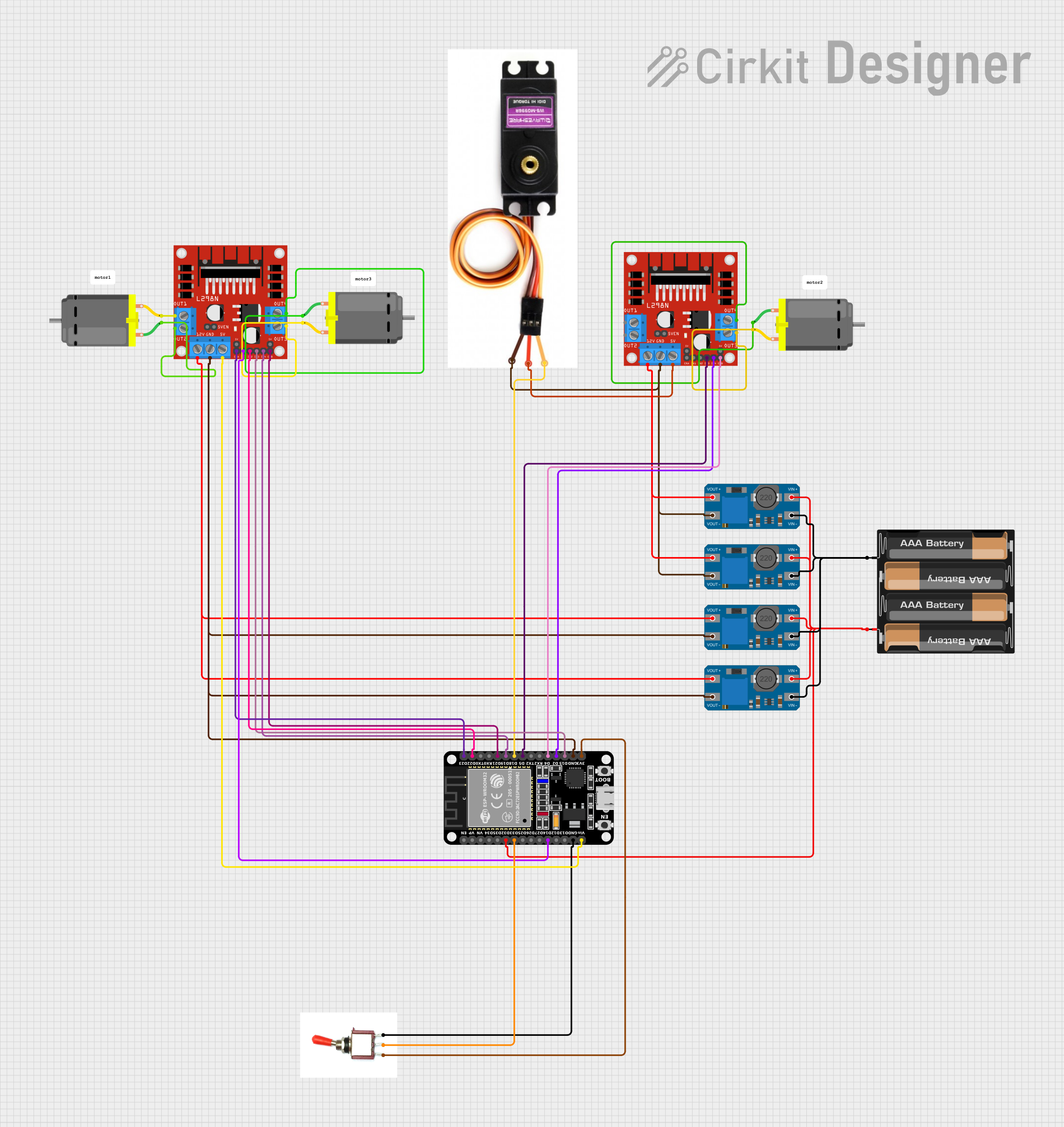


Explore Projects Built with MT3608
Common Applications
- Powering LEDs, sensors, and microcontrollers from low-voltage batteries
- Portable electronics and battery-powered devices
- Solar-powered systems
- DIY electronics projects requiring voltage conversion
Technical Specifications
The MT3608 is available as a module or as a standalone IC. Below are its key technical details:
Key Specifications
- Input Voltage Range: 2V to 24V
- Output Voltage Range: 2V to 28V (adjustable via a potentiometer on the module)
- Maximum Output Current: 2A (depending on input voltage and load conditions)
- Efficiency: Up to 93%
- Switching Frequency: 1.2 MHz
- Quiescent Current: 20 µA (typical)
- Operating Temperature: -40°C to +85°C
Pin Configuration (Standalone IC)
The MT3608 IC has 6 pins, as described in the table below:
| Pin Number | Pin Name | Description |
|---|---|---|
| 1 | SW | Switch pin. Connects to the inductor. |
| 2 | GND | Ground pin. Connect to the circuit ground. |
| 3 | FB | Feedback pin. Used to set the output voltage. |
| 4 | EN | Enable pin. High to enable the IC, low to disable. |
| 5 | VIN | Input voltage pin. Connect to the power source. |
| 6 | VOUT | Output voltage pin. Connect to the load. |
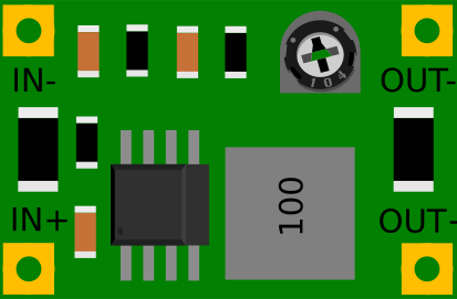
Pin Configuration (MT3608 Module)
The MT3608 module typically has 4 pins:
| Pin Name | Description |
|---|---|
| VIN | Input voltage pin. Connect to the power source. |
| GND | Ground pin. Connect to the circuit ground. |
| VOUT | Output voltage pin. Connect to the load. |
| EN | Enable pin. High to enable the module, low to disable. |
Usage Instructions
Using the MT3608 in a Circuit
- Connect the Input Voltage:
- Connect the positive terminal of your power source to the
VINpin. - Connect the negative terminal of your power source to the
GNDpin.
- Connect the positive terminal of your power source to the
- Connect the Output Voltage:
- Connect the
VOUTpin to the positive terminal of your load. - Connect the
GNDpin to the negative terminal of your load.
- Connect the
- Adjust the Output Voltage:
- Use the onboard potentiometer (on the module) to adjust the output voltage.
- Turn the potentiometer clockwise to increase the output voltage and counterclockwise to decrease it.
- Enable the Module:
- Ensure the
ENpin is connected to a high logic level (or left floating, as it is internally pulled up).
- Ensure the
Important Considerations
- Input Voltage: Ensure the input voltage is within the 2V to 24V range.
- Output Voltage: Do not exceed the maximum output voltage of 28V.
- Load Current: The maximum output current is 2A, but this depends on the input voltage and load conditions. Exceeding this limit may damage the module.
- Heat Dissipation: For high current loads, ensure proper heat dissipation to prevent overheating.
- Capacitors: Use appropriate input and output capacitors to stabilize the voltage and reduce noise.
Example: Using MT3608 with Arduino UNO
The MT3608 can be used to power an Arduino UNO from a low-voltage battery. Below is an example circuit and code:
Circuit Connections
- Connect the battery's positive terminal to the
VINpin of the MT3608 module. - Connect the battery's negative terminal to the
GNDpin of the MT3608 module. - Adjust the MT3608 output voltage to 5V using the potentiometer.
- Connect the
VOUTpin of the MT3608 to the5Vpin of the Arduino UNO. - Connect the
GNDpin of the MT3608 to theGNDpin of the Arduino UNO.
Example Code
// Example code to blink an LED using Arduino UNO powered by MT3608

const int ledPin = 13; // Pin connected to the onboard LED

void setup() {
  pinMode(ledPin, OUTPUT); // Set the LED pin as an output
}

void loop() {
  digitalWrite(ledPin, HIGH); // Turn the LED on
  delay(1000);                // Wait for 1 second
  digitalWrite(ledPin, LOW);  // Turn the LED off
  delay(1000);                // Wait for 1 second
}
Troubleshooting and FAQs
Common Issues
No Output Voltage:
- Ensure the input voltage is within the specified range (2V to 24V).
- Check the
ENpin. It should be high or left floating to enable the module. - Verify all connections are secure and correct.
Output Voltage is Incorrect:
- Adjust the potentiometer to set the desired output voltage.
- Ensure the feedback resistor network (if using the standalone IC) is configured correctly.
Overheating:
- Check if the load current exceeds the module's maximum rating (2A).
- Ensure proper heat dissipation, such as adding a heatsink or improving airflow.
Noise or Voltage Instability:
- Add appropriate input and output capacitors to stabilize the voltage.
- Ensure the inductor and capacitors meet the recommended specifications.
FAQs
Q1: Can the MT3608 step down voltage?
No, the MT3608 is a step-up (boost) converter and cannot step down voltage. For step-down applications, use a buck converter.
Q2: What is the efficiency of the MT3608?
The MT3608 has an efficiency of up to 93%, depending on the input voltage, output voltage, and load conditions.
Q3: Can I use the MT3608 to power a Raspberry Pi?
While the MT3608 can provide 5V output, it may not supply sufficient current for a Raspberry Pi under heavy load. Use a more robust power supply for such applications.
Q4: How do I calculate the output voltage?
For the standalone IC, the output voltage is determined by the feedback resistor network connected to the FB pin. Use the formula:
[ V_{OUT} = V_{REF} \times \left(1 + \frac{R1}{R2}\right) ]
where ( V_{REF} ) is typically 0.6V.