How to Use Control HMI: Examples, Pinouts, and Specs
Introduction
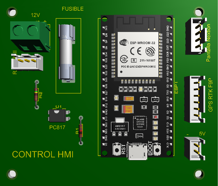
The Control HMI by EPY is a versatile Human-Machine Interface designed to facilitate seamless interaction between users and machinery or systems. It features a graphical display and input mechanisms such as touchscreens, buttons, or rotary encoders, enabling intuitive control and monitoring of industrial processes, automation systems, and other applications.
Explore Projects Built with Control HMI

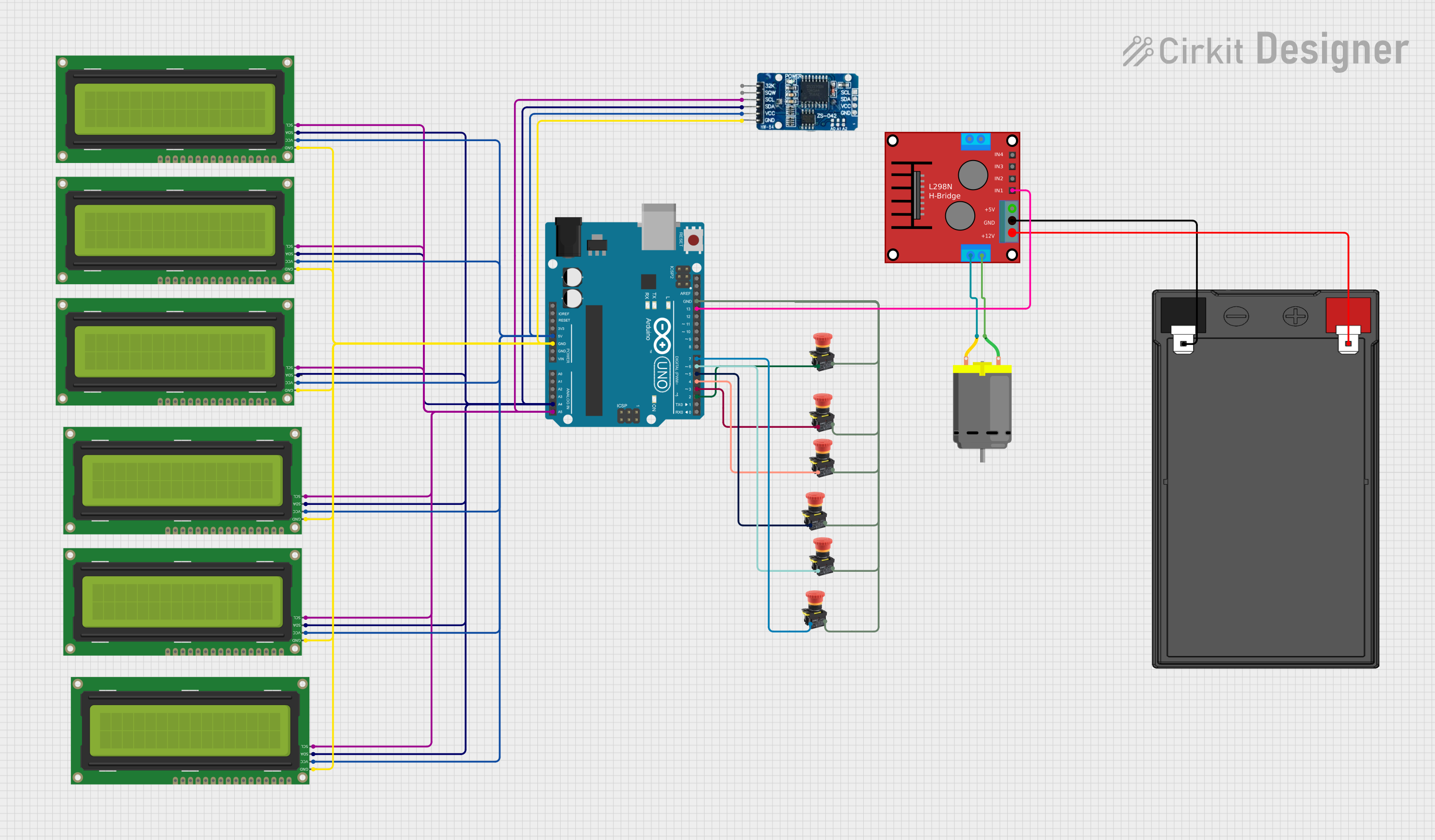


Explore Projects Built with Control HMI
Common Applications and Use Cases
- Industrial automation and process control
- Smart home systems and IoT device management
- Robotics control and monitoring
- Medical equipment interfaces
- Automotive dashboards and infotainment systems
Technical Specifications
The following table outlines the key technical details of the Control HMI:
| Parameter | Specification |
|---|---|
| Manufacturer | EPY |
| Part ID | Control HMI |
| Display Type | TFT LCD with capacitive touchscreen |
| Display Resolution | 800 x 480 pixels |
| Input Voltage | 5V DC (via USB) or 12-24V DC (via terminal) |
| Power Consumption | 5W (typical) |
| Communication Interfaces | UART, RS485, Ethernet, USB, CAN |
| Operating Temperature | -20°C to 70°C |
| Storage Temperature | -40°C to 85°C |
| Dimensions | 150mm x 90mm x 30mm |
| Mounting Options | Panel mount, VESA mount |
Pin Configuration and Descriptions
The Control HMI features a terminal block and communication ports for connectivity. Below is the pin configuration:
Terminal Block Pinout
| Pin | Name | Description |
|---|---|---|
| 1 | V+ | Positive DC input (12-24V) |
| 2 | V- | Ground (GND) |
| 3 | RS485 A | RS485 communication line A |
| 4 | RS485 B | RS485 communication line B |
| 5 | CAN H | CAN bus high line |
| 6 | CAN L | CAN bus low line |
USB Port
- Type: USB 2.0 (Type-B)
- Purpose: Firmware updates, data transfer, and power input (5V DC)
Ethernet Port
- Type: RJ45
- Purpose: Network communication for remote monitoring and control
Usage Instructions
How to Use the Control HMI in a Circuit
Power Connection:
- Connect a 12-24V DC power supply to the terminal block (V+ and V- pins).
- Alternatively, use a USB cable to power the device with 5V DC.
Communication Setup:
- For RS485 communication, connect the A and B lines to the corresponding pins on your controller or PLC.
- For CAN communication, connect the CAN H and CAN L lines to the CAN bus.
- Use the Ethernet port for network-based communication.
Mounting:
- Secure the HMI to a panel or VESA mount using the provided mounting brackets.
Programming:
- Use the manufacturer's software to design and upload graphical user interfaces (GUIs) to the HMI.
- Configure communication protocols and parameters (e.g., baud rate for RS485).
Important Considerations and Best Practices
- Ensure the power supply voltage matches the specified range (12-24V DC or 5V DC via USB).
- Use shielded cables for RS485 and CAN communication to minimize interference.
- Avoid exposing the HMI to direct sunlight or extreme temperatures beyond the operating range.
- Regularly update the firmware to access new features and security patches.
Example: Connecting to an Arduino UNO
The Control HMI can be connected to an Arduino UNO via the RS485 interface. Below is an example code snippet for sending data to the HMI:
#include <SoftwareSerial.h>

// Define RS485 communication pins
#define RS485_TX 10  // Arduino pin connected to RS485 TX
#define RS485_RX 11  // Arduino pin connected to RS485 RX
#define RS485_DE 9   // Arduino pin for RS485 Driver Enable

SoftwareSerial RS485(RS485_RX, RS485_TX); // RX, TX

void setup() {
  pinMode(RS485_DE, OUTPUT); // Set DE pin as output
  digitalWrite(RS485_DE, LOW); // Set DE to LOW (receive mode)

  RS485.begin(9600); // Initialize RS485 communication at 9600 baud
  Serial.begin(9600); // Initialize Serial Monitor for debugging
}

void loop() {
  // Send data to HMI
  digitalWrite(RS485_DE, HIGH); // Enable RS485 driver (transmit mode)
  RS485.print("Hello, HMI!");  // Send a message to the HMI
  digitalWrite(RS485_DE, LOW); // Disable RS485 driver (receive mode)

  delay(1000); // Wait for 1 second
}
Note: Ensure the RS485 A and B lines are correctly connected to the HMI.
Troubleshooting and FAQs
Common Issues and Solutions
HMI Does Not Power On:
- Verify the power supply voltage and connections.
- Check if the USB cable or terminal block is securely connected.
No Communication with Controller:
- Ensure the communication parameters (e.g., baud rate) match between the HMI and the controller.
- Check the wiring for RS485 or CAN connections.
Touchscreen Not Responding:
- Calibrate the touchscreen using the manufacturer's software.
- Ensure the screen is clean and free of debris.
Firmware Update Fails:
- Use a high-quality USB cable and ensure a stable power supply.
- Follow the firmware update instructions provided by EPY.
FAQs
Q1: Can the Control HMI be used outdoors?
A1: The HMI is not waterproof or weatherproof. Use it in a protected environment or within an enclosure.
Q2: What software is compatible with the Control HMI?
A2: EPY provides proprietary software for GUI design and configuration. Check the manufacturer's website for downloads.
Q3: Can I connect multiple HMIs to a single controller?
A3: Yes, you can connect multiple HMIs using RS485 or CAN bus, provided the communication protocol supports multi-device configurations.
Q4: How do I reset the HMI to factory settings?
A4: Refer to the user manual for the reset procedure, typically involving a combination of button presses or software commands.