
How to Use JST-03JQ-BT: Examples, Pinouts, and Specs
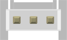
 Design with JST-03JQ-BT in Cirkit Designer
Introduction
The JST-03JQ-BT is a 3-pin connector manufactured by JST, designed for secure and reliable electrical connections in a variety of electronic applications. Its compact design and robust locking mechanism make it ideal for use in environments where space is limited, and a dependable connection is critical. This connector is commonly used in consumer electronics, industrial equipment, and hobbyist projects.
Explore Projects Built with JST-03JQ-BT
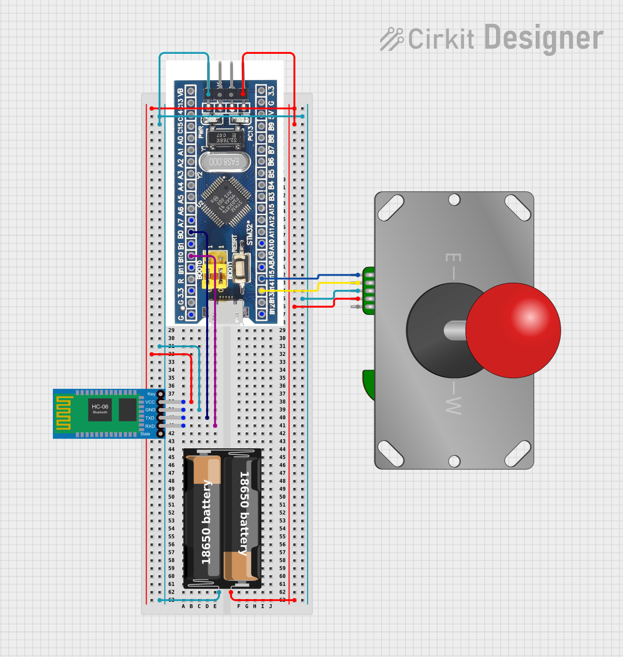 Open Project in Cirkit Designer
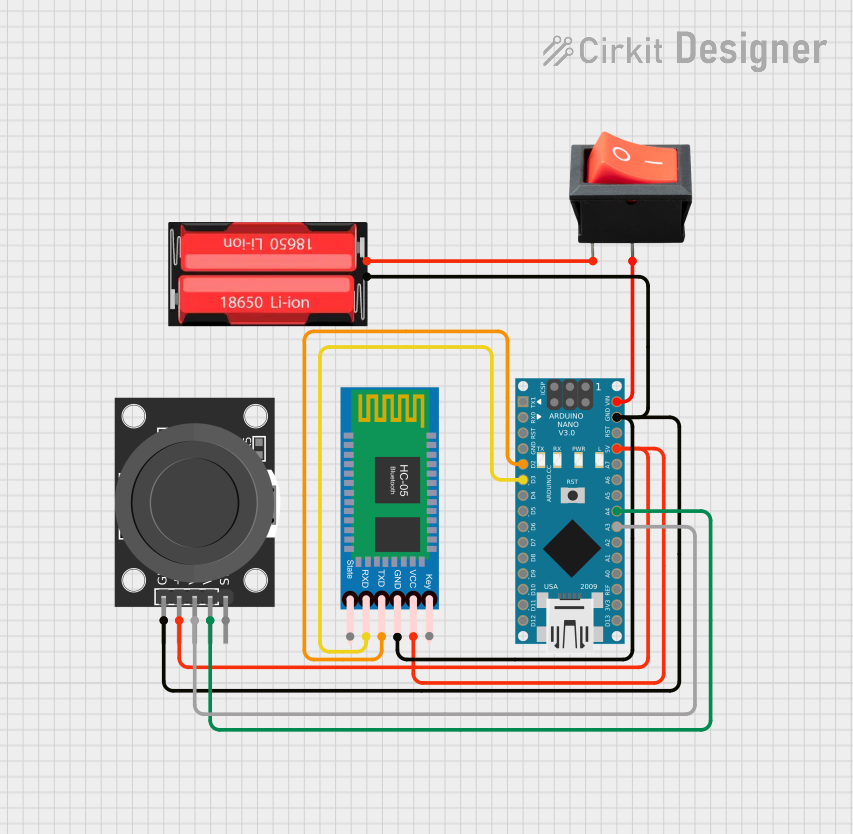 Open Project in Cirkit Designer
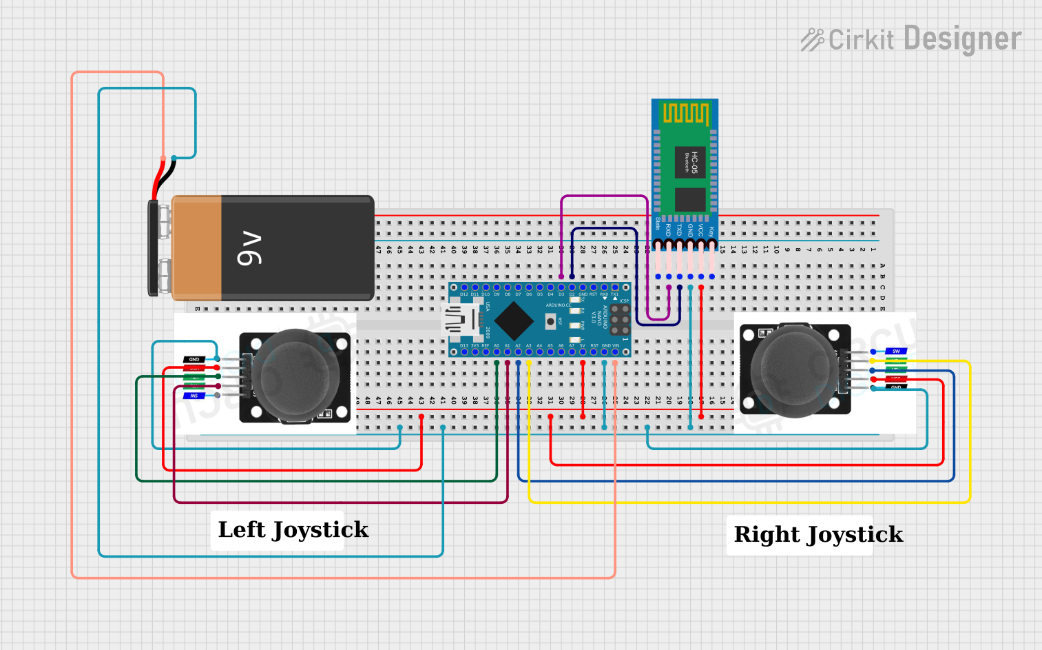 Open Project in Cirkit Designer
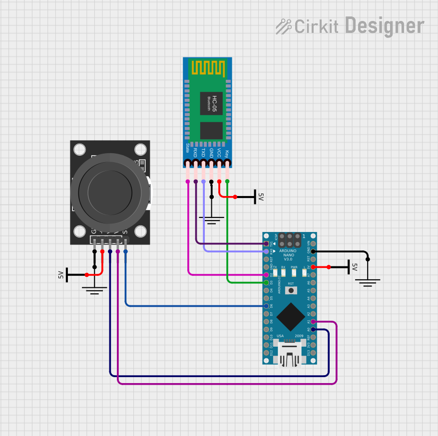 Open Project in Cirkit Designer
Explore Projects Built with JST-03JQ-BT
Open Project in Cirkit DesignerOpen Project in Cirkit DesignerOpen Project in Cirkit DesignerOpen Project in Cirkit DesignerCommon Applications
- Power delivery in small electronic devices
- Signal transmission in industrial control systems
- Connections in robotics and automation projects
- Prototyping and DIY electronics
Technical Specifications
Key Technical Details
| Parameter | Value |
|---|---|
| Manufacturer | JST |
| Part Number | 03JQ-BT |
| Number of Pins | 3 |
| Connector Type | Wire-to-board |
| Pitch | 2.5 mm |
| Current Rating | 3 A (maximum) |
| Voltage Rating | 250 V AC/DC (maximum) |
| Operating Temperature | -25°C to +85°C |
| Locking Mechanism | Yes (secure latch design) |
| Material | Housing: Nylon 66 (UL94V-0) |
Pin Configuration and Descriptions
The JST-03JQ-BT connector has three pins, typically used for power and signal connections. Below is the pinout configuration:
| Pin Number | Function | Description |
|---|---|---|
| 1 | VCC/Power | Positive voltage supply (e.g., +5V or +12V) |
| 2 | Signal/Ground | Signal or ground connection, depending on application |
| 3 | Ground/Return | Ground or return path for the circuit |
Usage Instructions
How to Use the JST-03JQ-BT in a Circuit
Connector Assembly:
- Crimp the appropriate terminals (e.g., JST SQ series) onto the wires using a crimping tool.
- Insert the crimped terminals into the housing of the JST-03JQ-BT until they click into place.
PCB Mounting:
- Ensure the mating connector on the PCB matches the 2.5 mm pitch of the JST-03JQ-BT.
- Solder the mating connector securely to the PCB.
Connection:
- Align the JST-03JQ-BT connector with the mating connector on the PCB.
- Push the connector until the locking mechanism clicks, ensuring a secure connection.
Disconnection:
- Press the latch on the connector to release the lock.
- Gently pull the connector apart without applying excessive force.
Important Considerations and Best Practices
- Wire Gauge: Use wires within the recommended range (e.g., 22–28 AWG) for optimal performance.
- Current and Voltage: Do not exceed the specified current (3 A) and voltage (250 V) ratings.
- Temperature: Operate the connector within the specified temperature range (-25°C to +85°C).
- Crimping: Use a proper crimping tool to ensure reliable electrical and mechanical connections.
- Mating Cycles: Avoid excessive mating/unmating cycles to prevent wear on the locking mechanism.
Example: Connecting to an Arduino UNO
The JST-03JQ-BT can be used to supply power or signals to an Arduino UNO. Below is an example of connecting a 5V power supply to the Arduino using this connector.
Circuit Diagram
- Pin 1 (VCC) → Arduino 5V pin
- Pin 2 (Signal/Ground) → Arduino GND pin
- Pin 3 (Ground) → Arduino GND pin (optional, for redundancy)
Sample Code
// Example code for reading a signal connected via the JST-03JQ-BT connector
// Pin 2 of the connector is used for the signal input to Arduino pin 7

const int signalPin = 7; // Signal connected to digital pin 7
int signalState = 0;     // Variable to store the signal state

void setup() {
  pinMode(signalPin, INPUT); // Set pin 7 as input
  Serial.begin(9600);       // Initialize serial communication
}

void loop() {
  signalState = digitalRead(signalPin); // Read the signal state
  Serial.print("Signal State: ");       // Print the signal state to the serial monitor
  Serial.println(signalState);
  delay(500); // Wait for 500 ms before reading again
}
Troubleshooting and FAQs
Common Issues and Solutions
Loose Connection:
- Issue: The connector does not stay securely in place.
- Solution: Ensure the terminals are fully inserted into the housing and the locking mechanism is engaged.
Intermittent Signal:
- Issue: Signal transmission is unreliable.
- Solution: Check for proper crimping of terminals and ensure wires are not damaged.
Overheating:
- Issue: The connector becomes hot during operation.
- Solution: Verify that the current and voltage do not exceed the specified ratings.
Connector Does Not Fit:
- Issue: The connector does not mate with the PCB connector.
- Solution: Confirm that the mating connector matches the 2.5 mm pitch and is compatible with the JST-03JQ-BT.
FAQs
Q: Can the JST-03JQ-BT be used for high-frequency signals?
- A: While it can handle low-frequency signals, it is not specifically designed for high-frequency applications. Consider using a connector designed for RF or high-speed data transmission.
Q: Is the JST-03JQ-BT waterproof?
- A: No, this connector is not waterproof. For outdoor or moisture-prone environments, use a waterproof connector.
Q: Can I reuse the connector housing?
- A: Yes, the housing can be reused, but ensure the terminals are not damaged during removal.
Q: What crimping tool should I use?
- A: Use a JST-compatible crimping tool, such as the WC-240 or similar, for best results.