How to Use ProtoSnap - Pro Mini: Examples, Pinouts, and Specs
Introduction
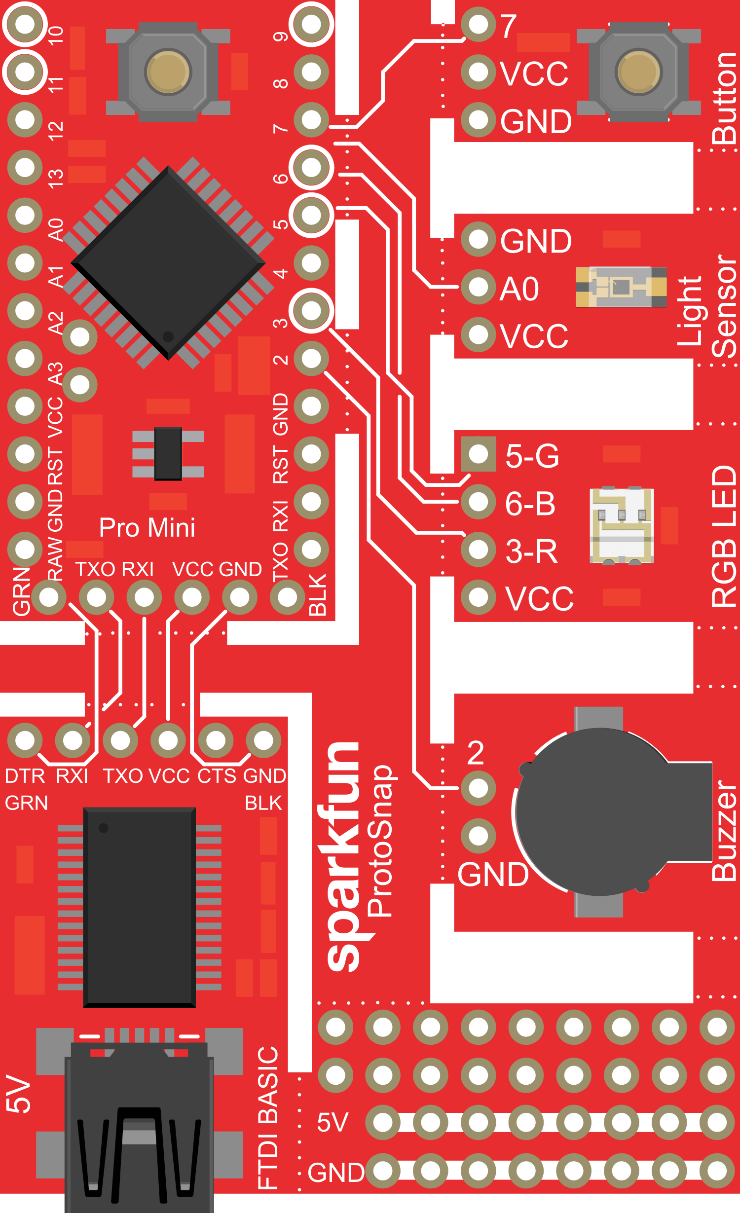
The ProtoSnap - Pro Mini is a versatile and compact prototyping platform that incorporates an Arduino Pro Mini at its heart. It is designed for hobbyists, educators, and developers to rapidly prototype and test Arduino-based projects. The board's layout facilitates easy snapping of components and modules, making it an ideal choice for experimenting without the need for soldering.
Explore Projects Built with ProtoSnap - Pro Mini

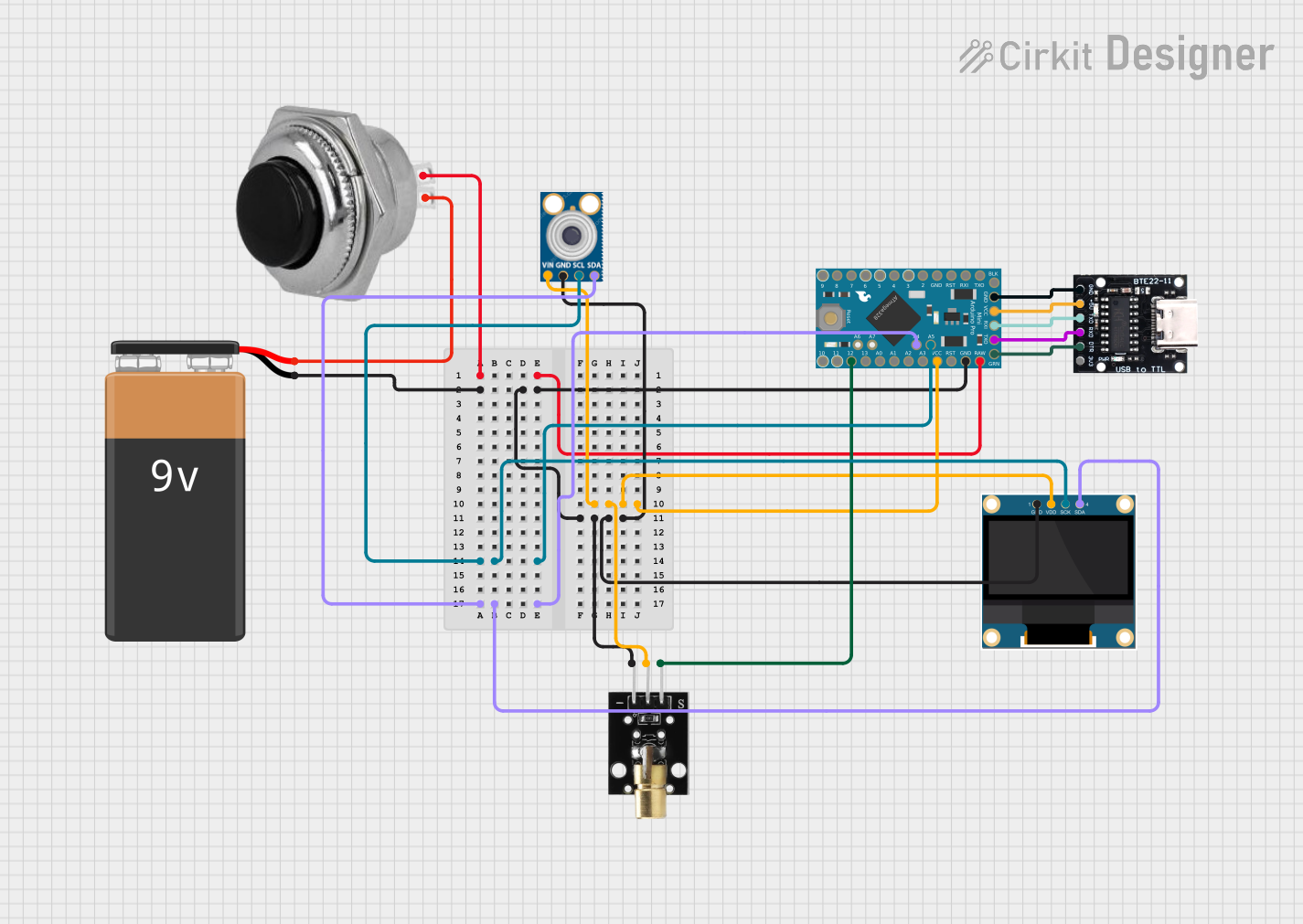
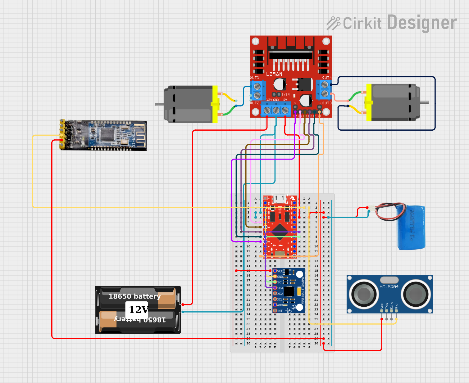
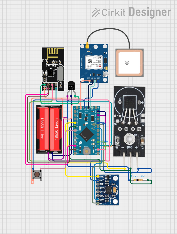
Explore Projects Built with ProtoSnap - Pro Mini
Common Applications and Use Cases
- Rapid prototyping of microcontroller-based projects
- Educational purposes for learning electronics and programming
- DIY electronics projects
- Wearable and embedded systems
- IoT (Internet of Things) applications
Technical Specifications
Key Technical Details
- Microcontroller: ATmega328
- Operating Voltage: 3.3V or 5V (depending on the model)
- Input Voltage (recommended): 7-12V
- Digital I/O Pins: 14 (of which 6 provide PWM output)
- Analog Input Pins: 6
- DC Current per I/O Pin: 40 mA
- Flash Memory: 32 KB (ATmega328) of which 0.5 KB used by bootloader
- SRAM: 2 KB (ATmega328)
- EEPROM: 1 KB (ATmega328)
- Clock Speed: 8 MHz (3.3V model) or 16 MHz (5V model)
Pin Configuration and Descriptions
| Pin Number | Function | Description |
|---|---|---|
| 1 | RESET | Used to reset the microcontroller |
| 2-13 | Digital Pins | Digital input/output, PWM output on pins 3, 5, 6, 9, 10, 11 |
| 14-19 | Analog Pins | Analog input pins A0-A5 |
| 20 | AREF | Analog reference voltage for the ADC |
| 21 | GND | Ground |
| 22 | RST | Reset pin, active low |
| 23 | VCC | Positive supply voltage for the microcontroller |
| 24 | GND | Ground |
| 25 | Raw | Raw input voltage for the onboard voltage regulator |
Usage Instructions
How to Use the Component in a Circuit
Powering the ProtoSnap - Pro Mini:
- Connect a 7-12V power supply to the 'Raw' pin for voltage regulation or supply regulated voltage directly to the 'VCC' pin.
Programming the ProtoSnap - Pro Mini:
- Connect the board to a computer using an FTDI breakout or similar serial converter.
- Select the correct board and port in the Arduino IDE.
- Upload your sketch using the Arduino IDE.
Connecting I/O Devices:
- Use the digital and analog pins to connect sensors, actuators, and other components.
- Ensure that the connected devices are compatible with the operating voltage of the ProtoSnap - Pro Mini.
Important Considerations and Best Practices
- Always disconnect the power source before making or altering connections.
- Double-check wiring to prevent shorts or incorrect connections.
- Use current-limiting resistors with LEDs and other sensitive components.
- Avoid drawing more than 40 mA from a single I/O pin.
- Ensure that the total current draw does not exceed the power supply's capability.
Troubleshooting and FAQs
Common Issues Users Might Face
- Sketch not uploading: Check the COM port and board selection in the Arduino IDE. Ensure the FTDI breakout or serial converter is properly connected.
- Incorrect behavior of connected devices: Verify the wiring and power supply. Check for code errors that may affect the device operation.
- Power issues: Ensure that the input voltage is within the recommended range. Check for any shorts or open circuits.
Solutions and Tips for Troubleshooting
- Use the onboard LED connected to pin 13 to test basic board functionality.
- Utilize serial print statements to debug and track code execution.
- If the board is unresponsive, try resetting the microcontroller using the RESET pin.
FAQs
Q: Can I use the ProtoSnap - Pro Mini at 5V and 3.3V? A: The ProtoSnap - Pro Mini comes in two variants, one for 3.3V and one for 5V. Choose the appropriate model for your project's voltage requirements.
Q: How do I connect the ProtoSnap - Pro Mini to my computer? A: Use an FTDI breakout or similar USB-to-serial converter to connect the board to your computer for programming.
Q: What is the maximum current the ProtoSnap - Pro Mini can handle? A: The board can handle up to 40 mA per I/O pin, but the total current should not exceed the capacity of the power supply and voltage regulator.
Example Code for Arduino UNO
// Blink the onboard LED connected to pin 13

void setup() {
  pinMode(13, OUTPUT); // Initialize pin 13 as an output
}

void loop() {
  digitalWrite(13, HIGH); // Turn on the LED
  delay(1000);            // Wait for a second
  digitalWrite(13, LOW);  // Turn off the LED
  delay(1000);            // Wait for a second
}
Note: The example code provided is for the Arduino UNO, which is compatible with the Arduino Pro Mini. Make sure to select the correct board (Arduino Pro Mini) in the Arduino IDE when uploading to the ProtoSnap - Pro Mini.