Cirkit Designer LogoCirkit DesignerYour all-in-one circuit design IDE Launch Cirkit Designer App

How to Use AS7261: Examples, Pinouts, and Specs

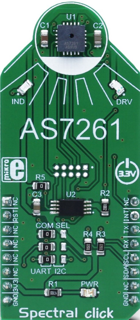
Image of AS7261Design with AS7261 in Cirkit Designer

Introduction

The AS7261 is a digital multispectral sensor designed to provide precise color measurements across the visible spectrum. This sensor is highly valued in applications requiring accurate color detection and analysis. Common use cases include:

Explore Projects Built with AS7261

Use Cirkit Designer to design, explore, and prototype these projects online. Some projects support real-time simulation. Click "Open Project" to start designing instantly!
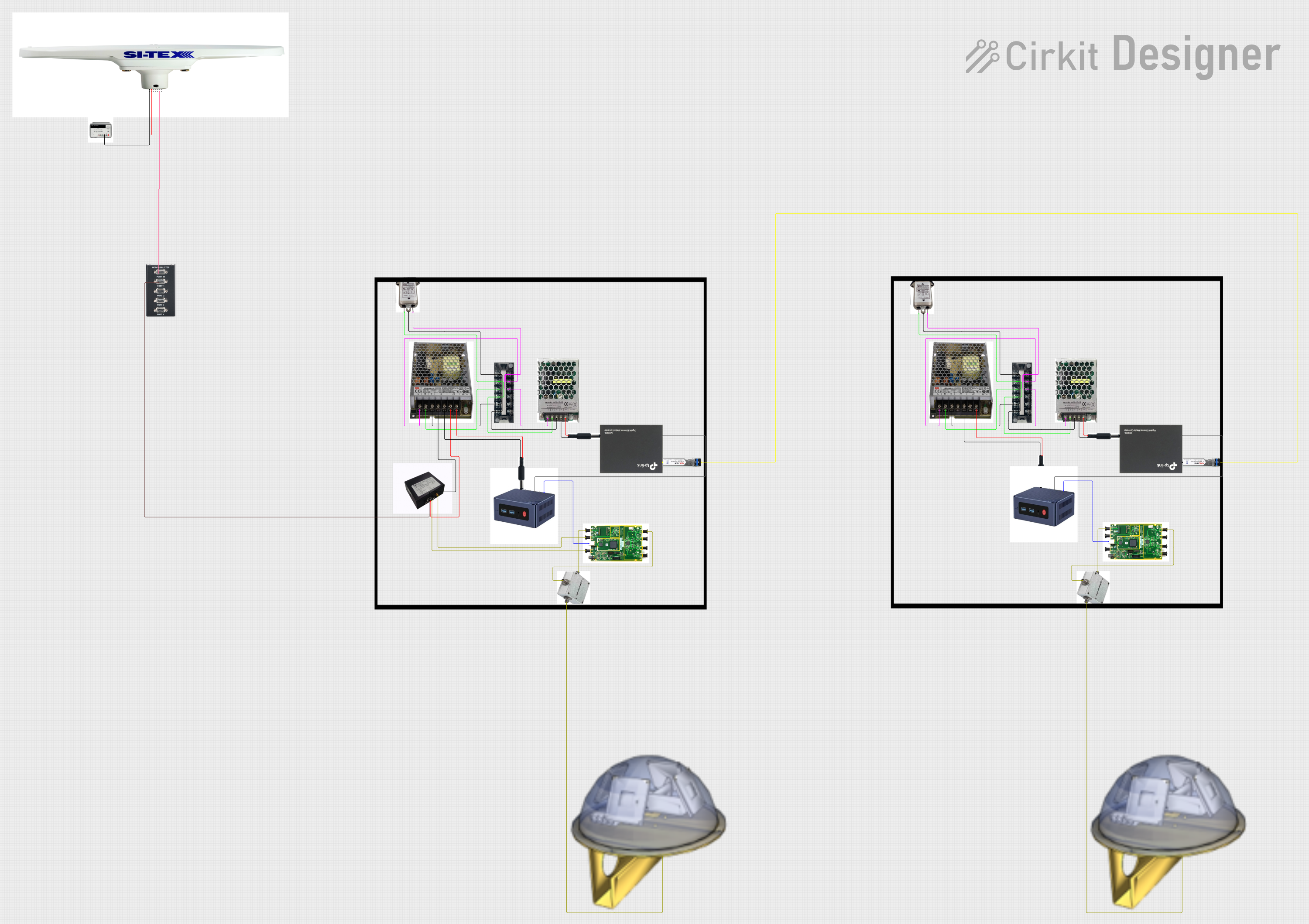
Image of Satellite-Based Timing and Navigation System with SDR and Atomic Clock Synchronization: A project utilizing AS7261 in a practical application
Satellite-Based Timing and Navigation System with SDR and Atomic Clock Synchronization

This circuit appears to be a complex system involving power supply management, GPS and timing synchronization, and data communication. It includes a SI-TEX G1 Satellite Compass for GPS data, an XHTF1021 Atomic Rubidium Clock for precise timing, and Ettus USRP B200 units for software-defined radio communication. Power is supplied through various SMPS units and distributed via terminal blocks and DC jacks. Data communication is facilitated by Beelink MINI S12 N95 computers, RS232 splitters, and a 1000BASE-T Media Converter for network connectivity. RF Directional Couplers are used to interface antennas with the USRP units, and the entire system is likely contained within cases for protection and organization.

Open Project in Cirkit Designer

Technical Specifications

Key Technical Details

Parameter Value
Supply Voltage 2.7V to 3.6V
Operating Current 100 µA (typical)
Spectral Range 450 nm to 650 nm
Interface I²C
Measurement Modes 6-channel visible spectrum
Operating Temperature -40°C to +85°C

Pin Configuration and Descriptions

Pin Number Pin Name Description
1 VDD Power Supply (2.7V to 3.6V)
2 GND Ground
3 SDA I²C Data Line
4 SCL I²C Clock Line
5 INT Interrupt Output
6 GPIO General Purpose Input/Output

Usage Instructions

How to Use the AS7261 in a Circuit

  1. Power Supply: Connect the VDD pin to a 3.3V power supply and the GND pin to ground.
  2. I²C Communication: Connect the SDA and SCL pins to the corresponding I²C pins on your microcontroller (e.g., Arduino UNO).
  3. Interrupts (Optional): Connect the INT pin to a digital input pin on your microcontroller if you wish to use interrupts.
  4. GPIO (Optional): The GPIO pin can be used for additional control or status signaling.

Important Considerations and Best Practices

Sample Arduino Code

Below is a sample code to interface the AS7261 with an Arduino UNO:

#include <Wire.h>

#define AS7261_ADDRESS 0x49 // I2C address of the AS7261

void setup() {
  Wire.begin(); // Initialize I2C communication
  Serial.begin(9600); // Initialize serial communication
  configureAS7261(); // Configure the AS7261 sensor
}

void loop() {
  readColorData(); // Read and print color data
  delay(1000); // Wait for 1 second before next reading
}

void configureAS7261() {
  Wire.beginTransmission(AS7261_ADDRESS);
  Wire.write(0x04); // Write to configuration register
  Wire.write(0x01); // Set configuration value
  Wire.endTransmission();
}

void readColorData() {
  Wire.beginTransmission(AS7261_ADDRESS);
  Wire.write(0x08); // Register to read color data
  Wire.endTransmission();
  Wire.requestFrom(AS7261_ADDRESS, 6); // Request 6 bytes of data

  if (Wire.available() == 6) {
    uint16_t red = Wire.read() << 8 | Wire.read(); // Read red channel
    uint16_t green = Wire.read() << 8 | Wire.read(); // Read green channel
    uint16_t blue = Wire.read() << 8 | Wire.read(); // Read blue channel

    Serial.print("Red: ");
    Serial.print(red);
    Serial.print(" Green: ");
    Serial.print(green);
    Serial.print(" Blue: ");
    Serial.println(blue);
  }
}

Troubleshooting and FAQs

Common Issues

  1. No Data Output:

    • Solution: Ensure the I²C connections are correct and the pull-up resistors are in place. Verify the sensor's power supply.
  2. Inaccurate Color Measurements:

    • Solution: Check for stable power supply and proper sensor placement. Ensure there are no obstructions or reflections affecting the sensor.
  3. I²C Communication Errors:

    • Solution: Verify the I²C address and ensure there are no address conflicts on the bus. Check the integrity of the SDA and SCL lines.

FAQs

Q1: Can the AS7261 be used with a 5V microcontroller?

Q2: How do I calibrate the AS7261 for accurate measurements?

Q3: Can the AS7261 measure UV or IR light?

By following this documentation, users can effectively integrate the AS7261 digital multispectral sensor into their projects, ensuring accurate and reliable color measurements.