How to Use 7 Segment Display(4 Digit): Examples, Pinouts, and Specs
Introduction
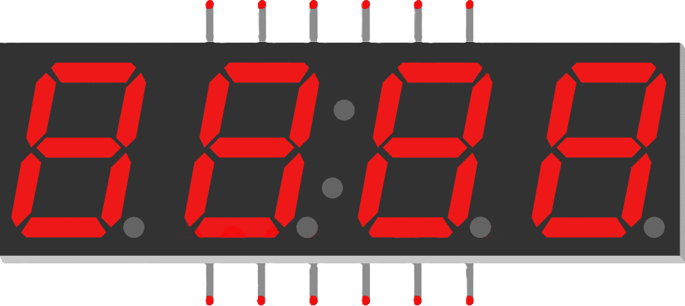
A 7-segment display is an electronic display device that consists of seven individual segments arranged in a rectangular fashion to represent numbers and some letters. Each segment is an LED or a series of LEDs that can be illuminated independently. The 4-digit 7-segment display is essentially four individual 7-segment displays that are connected together so that they can display values from 0000 to 9999. These displays are commonly used in digital clocks, electronic meters, and other devices that require numerical output to be shown to a user.
Explore Projects Built with 7 Segment Display(4 Digit)
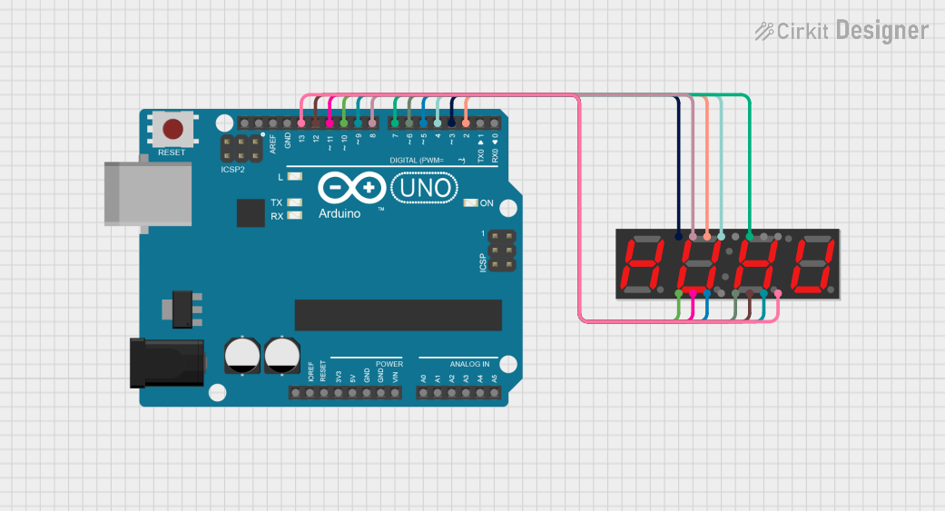
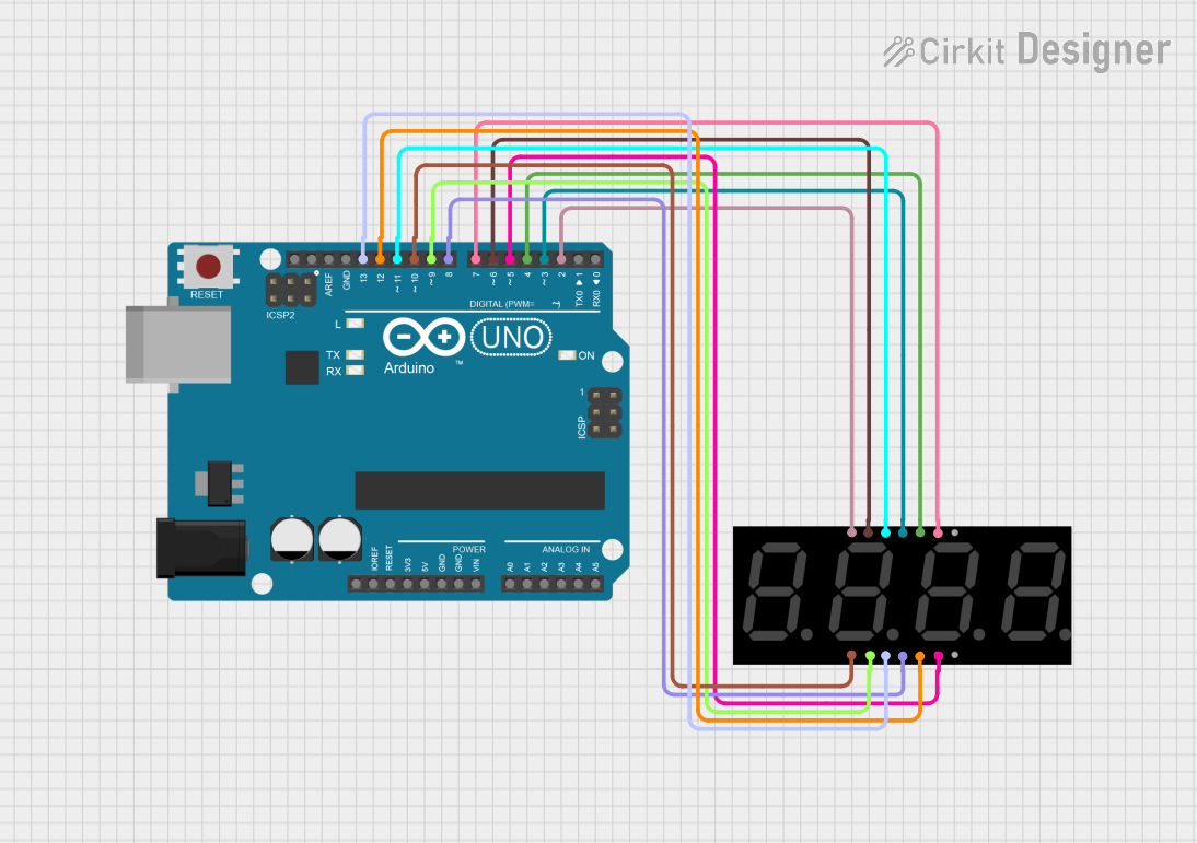
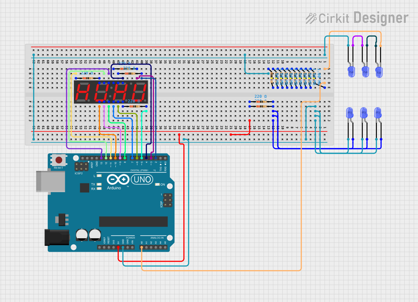
Explore Projects Built with 7 Segment Display(4 Digit)
Common Applications and Use Cases
- Digital clocks and timers
- Counters and number displays
- Electronic meters (like voltmeters, ammeters)
- Scoreboards and price displays
Technical Specifications
Key Technical Details
- Operating Voltage: Typically 3.3V to 5V
- Forward Current: 10-20 mA per segment
- Peak Wavelength: 655 nm (typical for red LEDs)
- Luminous Intensity: 80-100 mcd per segment (typical for red LEDs)
Pin Configuration and Descriptions
| Pin Number | Function | Description |
|---|---|---|
| 1 | Digit 1 (Common Anode/Cathode) | Controls the first digit (leftmost) |
| 2 | Segment E | Controls the middle segment on the left side |
| 3 | Segment D | Controls the bottom segment |
| 4 | Digit 2 (Common Anode/Cathode) | Controls the second digit |
| 5 | Segment C | Controls the middle segment on the right side |
| 6 | Decimal Point 1 | Controls the decimal point after first digit |
| 7 | Decimal Point 2 | Controls the decimal point after second digit |
| 8 | Ground/Common Anode/Cathode | Common ground or power depending on type |
| 9 | Decimal Point 3 | Controls the decimal point after third digit |
| 10 | Segment G | Controls the middle horizontal segment |
| 11 | Segment F | Controls the top segment on the left side |
| 12 | Digit 3 (Common Anode/Cathode) | Controls the third digit |
| 13 | Segment B | Controls the top segment on the right side |
| 14 | Segment A | Controls the top horizontal segment |
| 15 | Decimal Point 4 | Controls the decimal point after fourth digit |
| 16 | Digit 4 (Common Anode/Cathode) | Controls the fourth digit (rightmost) |
Usage Instructions
How to Use the Component in a Circuit
- Identify the Type: Determine if your 7-segment display is common anode or common cathode, as this will affect how you power the segments.
- Connect Power: Connect the common pins (1, 4, 12, 16) to either VCC or GND, depending on whether it's common anode or cathode.
- Resistors: Place a current-limiting resistor (220-470 ohms) in series with each segment pin to prevent damage to the LEDs.
- Control Pins: Connect the segment pins (A-G and decimal points) to the output pins of your microcontroller or driver IC.
- Programming: Write a program to control the individual segments to display the desired numbers.
Important Considerations and Best Practices
- Always use current-limiting resistors to prevent damage to the LEDs.
- Multiplexing can be used to control all four digits with fewer microcontroller pins.
- Ensure that the display is bright enough for the intended environment.
- Avoid powering all segments at maximum current simultaneously to prevent excessive power draw.
Example Code for Arduino UNO
// Define the Arduino pins connected to the segments
const int segA = 2;
const int segB = 3;
const int segC = 4;
const int segD = 5;
const int segE = 6;
const int segF = 7;
const int segG = 8;
// Define the Arduino pins connected to the digit control pins
const int digit1 = 9;
const int digit2 = 10;
const int digit3 = 11;
const int digit4 = 12;

void setup() {
  // Set all the segment and digit control pins as outputs
  for (int pin = 2; pin <= 12; pin++) {
    pinMode(pin, OUTPUT);
  }
  // Assuming a common anode display, turn off all segments
  clearDisplay();
}

void loop() {
  // Example: Display the number 1234
  displayNumber(1234);
  delay(1000); // Wait for 1 second
}

void displayNumber(int number) {
  // Break down the number into individual digits
  int thousands = (number / 1000) % 10;
  int hundreds = (number / 100) % 10;
  int tens = (number / 10) % 10;
  int ones = number % 10;

  // Display each digit for a short time to create the illusion of a static display
  displayDigit(thousands, digit1);
  delay(5);
  displayDigit(hundreds, digit2);
  delay(5);
  displayDigit(tens, digit3);
  delay(5);
  displayDigit(ones, digit4);
  delay(5);
}

void displayDigit(int digit, int digitPin) {
  // Turn off all digits
  digitalWrite(digit1, HIGH);
  digitalWrite(digit2, HIGH);
  digitalWrite(digit3, HIGH);
  digitalWrite(digit4, HIGH);

  // Turn on the appropriate segments for this digit
  switch (digit) {
    case 0: writeSegments(B11111100); break;
    case 1: writeSegments(B01100000); break;
    case 2: writeSegments(B11011010); break;
    case 3: writeSegments(B11110010); break;
    case 4: writeSegments(B01100110); break;
    case 5: writeSegments(B10110110); break;
    case 6: writeSegments(B10111110); break;
    case 7: writeSegments(B11100000); break;
    case 8: writeSegments(B11111110); break;
    case 9: writeSegments(B11110110); break;
  }

  // Turn on this digit
  digitalWrite(digitPin, LOW);
}

void writeSegments(byte segments) {
  // Write each segment pin HIGH or LOW based on the byte pattern
  digitalWrite(segA, segments & B10000000 ? LOW : HIGH);
  digitalWrite(segB, segments & B01000000 ? LOW : HIGH);
  digitalWrite(segC, segments & B00100000 ? LOW : HIGH);
  digitalWrite(segD, segments & B00010000 ? LOW : HIGH);
  digitalWrite(segE, segments & B00001000 ? LOW : HIGH);
  digitalWrite(segF, segments & B00000100 ? LOW : HIGH);
  digitalWrite(segG, segments & B00000010 ? LOW : HIGH);
}

void clearDisplay() {
  // Turn off all segments
  writeSegments(B00000000);
  // Turn off all digits
  digitalWrite(digit1, HIGH);
  digitalWrite(digit2, HIGH);
  digitalWrite(digit3, HIGH);
  digitalWrite(digit4, HIGH);
}
Troubleshooting and FAQs
Common Issues Users Might Face
- Segments not lighting up: Check the connections and ensure that the current-limiting resistors are in place.
- Dim display: Ensure that the power supply is adequate and that the resistors are of the correct value.
- Incorrect numbers displayed: Verify the segment control logic in your code.
Solutions and Tips for Troubleshooting
- Double-check wiring against the pin configuration table.
- Use a multimeter to verify that each segment is receiving power when it should.
- If using multiplexing, ensure that the timing is correct to prevent ghosting or flickering.
FAQs
Q: Can I use a 5V supply with a 3.3V 7-segment display? A: Yes, but you must use appropriate current-limiting resistors to prevent damage.
Q: How can I display letters on the 7-segment display? A: Some letters can be approximated using the segments (e.g., 'A' can be displayed using segments A, B, C, E, F, G), but not all letters can be represented due to the limited number of segments.
Q: Can I control multiple 7-segment displays with one Arduino? A: Yes, you can control multiple displays using multiplexing or by using shift registers to expand the number of available output pins.