How to Use probe pins: Examples, Pinouts, and Specs
Introduction
Probe pins are essential components used for making temporary electrical connections to test points on a circuit board. They are designed to allow engineers and technicians to access signals, voltages, and other electrical parameters for measurement, debugging, and testing purposes. These pins are commonly used in prototyping, troubleshooting, and quality control processes in electronics manufacturing and repair.
Explore Projects Built with probe pins


Explore Projects Built with probe pins
Common Applications and Use Cases
- Debugging and testing circuit boards during development.
- Measuring voltages, currents, and signals in electronic circuits.
- Temporary connections for prototyping and experimentation.
- Quality assurance testing in manufacturing environments.
- Accessing hard-to-reach test points on densely populated PCBs.
Technical Specifications
Probe pins come in various sizes, materials, and configurations depending on the application. Below are the general specifications for standard probe pins:
General Specifications
| Parameter | Value/Description |
|---|---|
| Material | Brass, phosphor bronze, or stainless steel |
| Plating | Gold, nickel, or tin for corrosion resistance |
| Contact Resistance | Typically < 50 mΩ |
| Current Rating | 1A to 5A (varies by model) |
| Operating Temperature | -40°C to +125°C |
| Durability | 10,000 to 1,000,000 cycles (depends on type) |
Pin Configuration and Descriptions
Probe pins do not have a standard pinout like ICs, but they are categorized based on their design and usage. Below is a table describing common types of probe pins:
| Type | Description |
|---|---|
| Spring-loaded pins | Feature a spring mechanism for reliable contact. |
| Pogo pins | A type of spring-loaded pin with a rounded tip. |
| Needle-point pins | Sharp tips for penetrating solder masks or oxides. |
| Flat-tip pins | Flat contact surface for larger test points. |
| Hook-style pins | Designed to latch onto wires or components. |
Usage Instructions
How to Use Probe Pins in a Circuit
- Identify Test Points: Locate the test points on the circuit board where measurements are required. These are often labeled or marked on the PCB.
- Select the Appropriate Probe Pin: Choose a probe pin type that matches the test point size and shape (e.g., needle-point for small pads, flat-tip for larger areas).
- Connect the Probe Pin: Attach the probe pin to the test point. Ensure a secure and stable connection to avoid intermittent readings.
- Measure Signals: Connect the other end of the probe pin to the measurement device (e.g., multimeter, oscilloscope) and take the required readings.
- Remove After Use: Disconnect the probe pin carefully to avoid damaging the test point or PCB.
Important Considerations and Best Practices
- Avoid Excessive Force: Applying too much pressure can damage the test point or PCB.
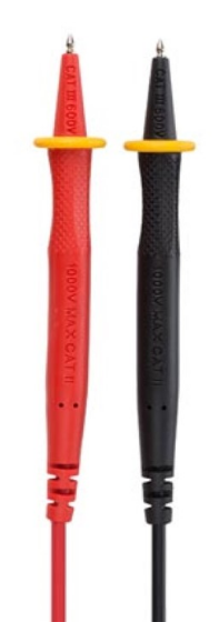
- Use Insulated Probes: For safety, especially when working with high voltages, use probe pins with insulated handles.
- Minimize Signal Interference: Keep probe wires short to reduce noise and signal degradation.
- Clean Contact Points: Ensure the test points and probe tips are clean for accurate measurements.
- Secure Connections: Use clips or holders to stabilize the probe pin during long measurements.
Example: Using Probe Pins with an Arduino UNO
Probe pins can be used to measure signals on an Arduino UNO board. For example, you can measure the PWM signal on pin 9 using an oscilloscope.
// Example code to generate a PWM signal on Arduino UNO pin 9
// This code sets up a PWM signal with a 50% duty cycle and 1 kHz frequency.

void setup() {
  pinMode(9, OUTPUT); // Set pin 9 as an output
  analogWrite(9, 128); // Write a 50% duty cycle (128 out of 255)
}

void loop() {
  // No need to add code here; the PWM signal runs continuously
}
Note: Use a needle-point probe pin to connect to pin 9 on the Arduino UNO for accurate signal measurement.
Troubleshooting and FAQs
Common Issues and Solutions
| Issue | Solution |
|---|---|
| Intermittent Readings | Ensure the probe pin is making firm contact with the test point. |
| Signal Noise or Distortion | Use shorter probe wires and ensure proper grounding. |
| Damaged Test Points | Avoid excessive force and use the correct probe tip type. |
| Corrosion on Probe Tips | Clean the probe tips with isopropyl alcohol or a fine abrasive. |
| Probe Pin Slipping Off | Use clips or holders to stabilize the probe pin. |
FAQs
Can probe pins be used for high-frequency signals?
- Yes, but ensure the probe pin and connecting wires are designed for high-frequency applications to minimize signal loss.
What is the lifespan of a probe pin?
- The lifespan depends on the type and usage but typically ranges from 10,000 to 1,000,000 cycles.
Are probe pins safe for high-voltage applications?
- Only use probe pins rated for the voltage level you are working with. Insulated probe pins are recommended for high-voltage applications.
How do I choose the right probe pin for my application?
- Consider the size and shape of the test point, the required current rating, and the environmental conditions (e.g., temperature, humidity).
By following this documentation, you can effectively use probe pins for testing and debugging electronic circuits.