Cirkit Designer Logo
Cirkit Designer
Your all-in-one circuit design IDE
Home / 
Component Documentation

How to Use Split-Core Hall Effect Current Sensor: Examples, Pinouts, and Specs

Image of Split-Core Hall Effect Current Sensor
Cirkit Designer LogoDesign with Split-Core Hall Effect Current Sensor in Cirkit Designer

Introduction

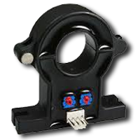
The Split-Core Hall Effect Current Sensor is a device designed to measure the current flowing through a conductor by detecting the magnetic field generated by the current. Its split-core design allows for easy installation around existing wires without requiring disconnection, making it ideal for non-invasive current measurement. This sensor is widely used in applications such as energy monitoring, industrial automation, motor control, and renewable energy systems.

Common applications include:

  • Monitoring AC and DC currents in power systems
  • Measuring current in electric motors and generators
  • Energy consumption tracking in residential and industrial setups
  • Overcurrent protection in electrical circuits

Explore Projects Built with Split-Core Hall Effect Current Sensor

Use Cirkit Designer to design, explore, and prototype these projects online. Some projects support real-time simulation. Click "Open Project" to start designing instantly!
Arduino Mega 2560 Hall Sensor Interface for Real-Time Magnetic Field Detection
Image of Hall Effect CD: A project utilizing Split-Core Hall Effect Current Sensor in a practical application
This circuit uses an Arduino Mega 2560 to read data from a Hall Sensor, which is powered through a terminal block connected to the Arduino's 5V supply. The sensor's ground is connected to the Arduino's ground, and its signal output is read by the Arduino on pin D2.
Cirkit Designer LogoOpen Project in Cirkit Designer
ESP32-Based Current Monitoring and Temperature Sensing System
Image of SISTEMA DE MONITOREO: A project utilizing Split-Core Hall Effect Current Sensor in a practical application
This circuit is designed to measure current using an ACS712 Current Sensor and temperature using a DS18B20 sensor, with an ESP32 microcontroller to process and possibly communicate the sensor data. The ACS712 sensor output is connected to one of the ESP32's analog input pins (D34), while the DS18B20's signal line is interfaced with a digital input pin (D23) through a pull-up resistor (4.7k Ohms). The ESP32 is powered through its Vin pin, and both sensors share a common ground with the ESP32.
Cirkit Designer LogoOpen Project in Cirkit Designer
ESP32-Controlled Smart Lighting System with Power Monitoring
Image of Energy Monitoring System: A project utilizing Split-Core Hall Effect Current Sensor in a practical application
This circuit appears to be a multi-channel current monitoring system using several ACS712 current sensors to measure the current through different loads, likely bulbs connected to a 220V power source. The current readings from the sensors are digitized by an Adafruit ADS1115 16-bit ADC, which interfaces with an ESP32 microcontroller via I2C communication for further processing or telemetry. A buck converter is used to step down the voltage to power the ESP32 and the sensors, and the system is powered through a 2.1mm DC barrel jack, indicating it is designed for external power supply.
Cirkit Designer LogoOpen Project in Cirkit Designer
Wemos S2 Mini Controlled Smart Device with OLED Display, Thermal Printing, and RGB LED Strip
Image of DT NEA - Noah Patel: A project utilizing Split-Core Hall Effect Current Sensor in a practical application
This circuit features a Wemos S2 Mini microcontroller that controls a WS2812 RGB LED strip and communicates with a 0.96" OLED display and a 58mm mini thermal printer. The ACS712 Current Sensor is interfaced with the microcontroller to monitor current, and power is managed by a CD42 BMS connected to two 18650 Li-ion batteries, with a USB-C PD Trigger Board for power delivery. The circuit is designed for visual output (LED strip, OLED display), printing capabilities, and current sensing, likely for a portable, battery-powered monitoring and display device.
Cirkit Designer LogoOpen Project in Cirkit Designer

Explore Projects Built with Split-Core Hall Effect Current Sensor

Use Cirkit Designer to design, explore, and prototype these projects online. Some projects support real-time simulation. Click "Open Project" to start designing instantly!
Image of Hall Effect CD: A project utilizing Split-Core Hall Effect Current Sensor in a practical application
Arduino Mega 2560 Hall Sensor Interface for Real-Time Magnetic Field Detection
This circuit uses an Arduino Mega 2560 to read data from a Hall Sensor, which is powered through a terminal block connected to the Arduino's 5V supply. The sensor's ground is connected to the Arduino's ground, and its signal output is read by the Arduino on pin D2.
Cirkit Designer LogoOpen Project in Cirkit Designer
Image of SISTEMA DE MONITOREO: A project utilizing Split-Core Hall Effect Current Sensor in a practical application
ESP32-Based Current Monitoring and Temperature Sensing System
This circuit is designed to measure current using an ACS712 Current Sensor and temperature using a DS18B20 sensor, with an ESP32 microcontroller to process and possibly communicate the sensor data. The ACS712 sensor output is connected to one of the ESP32's analog input pins (D34), while the DS18B20's signal line is interfaced with a digital input pin (D23) through a pull-up resistor (4.7k Ohms). The ESP32 is powered through its Vin pin, and both sensors share a common ground with the ESP32.
Cirkit Designer LogoOpen Project in Cirkit Designer
Image of Energy Monitoring System: A project utilizing Split-Core Hall Effect Current Sensor in a practical application
ESP32-Controlled Smart Lighting System with Power Monitoring
This circuit appears to be a multi-channel current monitoring system using several ACS712 current sensors to measure the current through different loads, likely bulbs connected to a 220V power source. The current readings from the sensors are digitized by an Adafruit ADS1115 16-bit ADC, which interfaces with an ESP32 microcontroller via I2C communication for further processing or telemetry. A buck converter is used to step down the voltage to power the ESP32 and the sensors, and the system is powered through a 2.1mm DC barrel jack, indicating it is designed for external power supply.
Cirkit Designer LogoOpen Project in Cirkit Designer
Image of DT NEA - Noah Patel: A project utilizing Split-Core Hall Effect Current Sensor in a practical application
Wemos S2 Mini Controlled Smart Device with OLED Display, Thermal Printing, and RGB LED Strip
This circuit features a Wemos S2 Mini microcontroller that controls a WS2812 RGB LED strip and communicates with a 0.96" OLED display and a 58mm mini thermal printer. The ACS712 Current Sensor is interfaced with the microcontroller to monitor current, and power is managed by a CD42 BMS connected to two 18650 Li-ion batteries, with a USB-C PD Trigger Board for power delivery. The circuit is designed for visual output (LED strip, OLED display), printing capabilities, and current sensing, likely for a portable, battery-powered monitoring and display device.
Cirkit Designer LogoOpen Project in Cirkit Designer

Technical Specifications

Below are the key technical details of the Split-Core Hall Effect Current Sensor:

Parameter Value
Measurement Range ±50A to ±200A (varies by model)
Supply Voltage 5V DC
Output Signal Analog voltage (proportional to current)
Accuracy ±1% of full-scale reading
Bandwidth DC to 20 kHz
Operating Temperature -40°C to +85°C
Core Design Split-core for easy installation
Isolation Voltage 2.5 kV RMS

Pin Configuration and Descriptions

The sensor typically comes with a 3-pin interface. The pinout is as follows:

Pin Name Description
1 VCC Power supply input (5V DC)
2 GND Ground connection
3 OUT Analog output voltage proportional to measured current

Usage Instructions

How to Use the Sensor in a Circuit

  1. Power the Sensor: Connect the VCC pin to a 5V DC power supply and the GND pin to the ground of your circuit.
  2. Install the Sensor: Open the split-core clamp and place it around the conductor whose current you want to measure. Ensure the conductor is centered within the core for accurate readings.
  3. Read the Output: The OUT pin provides an analog voltage proportional to the current flowing through the conductor. This output can be read using an analog-to-digital converter (ADC) on a microcontroller or data acquisition system.

Important Considerations and Best Practices

  • Polarity: Ensure the current direction matches the sensor's orientation markings for correct readings.
  • Conductor Placement: Position the conductor in the center of the split-core for optimal accuracy.
  • Noise Reduction: Use proper shielding and grounding techniques to minimize noise in the output signal.
  • Calibration: For precise measurements, calibrate the sensor using a known current source.
  • Avoid Overloading: Do not exceed the sensor's maximum current rating to prevent damage.

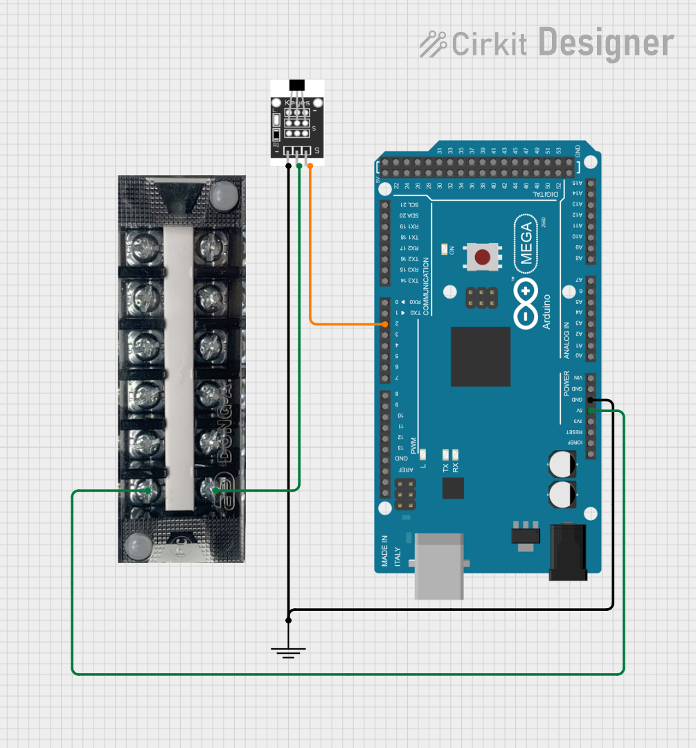
Example: Connecting to an Arduino UNO

Below is an example of how to use the Split-Core Hall Effect Current Sensor with an Arduino UNO to measure current:

// Define the analog pin connected to the sensor's OUT pin
const int sensorPin = A0;

// Define the sensor's sensitivity (e.g., 40mV/A for a ±50A sensor)
const float sensitivity = 0.04; // Sensitivity in volts per ampere

void setup() {
  Serial.begin(9600); // Initialize serial communication
}

void loop() {
  // Read the analog voltage from the sensor
  int sensorValue = analogRead(sensorPin);
  
  // Convert the analog reading (0-1023) to a voltage (0-5V)
  float voltage = sensorValue * (5.0 / 1023.0);
  
  // Calculate the current in amperes
  float current = voltage / sensitivity;
  
  // Print the current to the Serial Monitor
  Serial.print("Current: ");
  Serial.print(current);
  Serial.println(" A");
  
  delay(1000); // Wait for 1 second before the next reading
}

Troubleshooting and FAQs

Common Issues and Solutions

  1. No Output Signal:

    • Cause: Incorrect wiring or insufficient power supply.
    • Solution: Verify that the VCC and GND pins are properly connected to a 5V DC power source.
  2. Inaccurate Readings:

    • Cause: Misalignment of the conductor within the split-core.
    • Solution: Ensure the conductor is centered in the core and the sensor is properly oriented.
  3. Excessive Noise in Output:

    • Cause: Electromagnetic interference or poor grounding.
    • Solution: Use shielded cables and ensure a solid ground connection.
  4. Output Voltage Exceeds Expected Range:

    • Cause: Current exceeds the sensor's maximum rating.
    • Solution: Verify that the current is within the sensor's specified range.

FAQs

Q: Can this sensor measure both AC and DC currents?
A: Yes, the Split-Core Hall Effect Current Sensor can measure both AC and DC currents.

Q: Is the sensor safe to use with high-voltage conductors?
A: Yes, the sensor provides electrical isolation up to 2.5 kV RMS, making it safe for use with high-voltage systems.

Q: How do I calibrate the sensor?
A: To calibrate, pass a known current through the conductor and measure the output voltage. Use this data to calculate the sensor's sensitivity.

Q: Can I use this sensor with a 3.3V microcontroller?
A: While the sensor requires a 5V supply, its output can be interfaced with a 3.3V microcontroller using a voltage divider or level shifter.

By following this documentation, you can effectively integrate the Split-Core Hall Effect Current Sensor into your projects for accurate and reliable current measurement.