How to Use ADS1232 Module: Examples, Pinouts, and Specs
Introduction
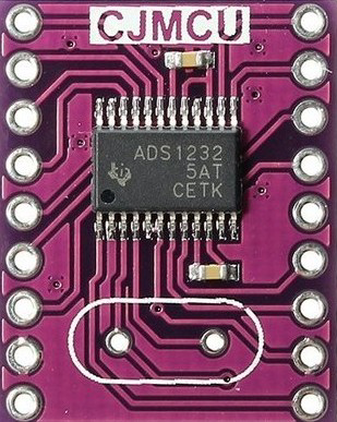
The ADS1232 is a high-precision, 24-bit analog-to-digital converter (ADC) manufactured by Texas Instruments. It is specifically designed for applications requiring high accuracy and low noise, such as weighing scales and industrial process control systems. The module integrates a low-noise programmable gain amplifier (PGA), an internal oscillator, and a precision voltage reference, making it an ideal choice for high-resolution measurements.
Explore Projects Built with ADS1232 Module


Explore Projects Built with ADS1232 Module
Common Applications and Use Cases
- Digital weighing scales
- Industrial process control systems
- Medical instrumentation
- Temperature measurement systems
- Strain gauge and load cell applications
Technical Specifications
The ADS1232 module offers a range of features and specifications that make it suitable for precision measurement tasks. Below are the key technical details:
Key Technical Details
- Resolution: 24-bit
- Input Channels: 2 differential or 4 single-ended
- Input Voltage Range: ±VREF / Gain
- Programmable Gain: 1, 2, 64, 128
- Data Rate: 10 SPS or 80 SPS (selectable)
- Voltage Reference: Internal or external (2.5V internal reference)
- Power Supply Voltage: 2.7V to 5.3V
- Current Consumption: 1.4mA (typical at 5V)
- Operating Temperature Range: -40°C to +85°C
- Noise Performance: 17nV (rms) at 10 SPS, Gain = 128
- Interface: SPI-compatible serial interface
Pin Configuration and Descriptions
The ADS1232 module typically comes with a 16-pin configuration. Below is the pinout and description:
| Pin Name | Pin Number | Description |
|---|---|---|
| AVDD | 1 | Analog power supply (2.7V to 5.3V) |
| AGND | 2 | Analog ground |
| AINP1 | 3 | Positive input for differential channel 1 |
| AINN1 | 4 | Negative input for differential channel 1 |
| AINP2 | 5 | Positive input for differential channel 2 |
| AINN2 | 6 | Negative input for differential channel 2 |
| REFP | 7 | Positive reference voltage input |
| REFN | 8 | Negative reference voltage input |
| DVDD | 9 | Digital power supply (2.7V to 5.3V) |
| DGND | 10 | Digital ground |
| SCLK | 11 | Serial clock input for SPI communication |
| DOUT/DRDY | 12 | Data output and data ready signal |
| SPEED | 13 | Data rate selection (LOW = 10 SPS, HIGH = 80 SPS) |
| GAIN0 | 14 | Gain selection bit 0 |
| GAIN1 | 15 | Gain selection bit 1 |
| PDWN | 16 | Power-down control (LOW = Power-down mode, HIGH = Normal operation) |
Usage Instructions
The ADS1232 module is straightforward to use in precision measurement applications. Below are the steps and considerations for integrating it into a circuit.
How to Use the ADS1232 in a Circuit
- Power Supply: Connect AVDD and DVDD to a stable power source (2.7V to 5.3V). Connect AGND and DGND to the ground.
- Input Connections:
- For differential measurements, connect the positive and negative inputs (AINP1/AINN1 or AINP2/AINN2) to the sensor or signal source.
- For single-ended measurements, connect the signal to AINP and ground AINN.
- Reference Voltage: Use the internal 2.5V reference or connect an external reference voltage to REFP and REFN.
- Gain and Data Rate: Configure the gain and data rate using the GAIN0, GAIN1, and SPEED pins.
- SPI Communication: Connect the SCLK and DOUT/DRDY pins to the microcontroller for data transfer.
- Power-Down Mode: Use the PDWN pin to enable or disable power-down mode.
Important Considerations and Best Practices
- Use decoupling capacitors (e.g., 0.1µF and 10µF) close to the power supply pins to reduce noise.
- Ensure proper grounding to minimize noise and interference.
- For high-accuracy applications, use a stable and low-noise external reference voltage.
- Shield the input signal lines to prevent electromagnetic interference (EMI).
- Avoid exceeding the input voltage range to prevent damage to the ADC.
Example: Connecting ADS1232 to Arduino UNO
Below is an example of how to interface the ADS1232 with an Arduino UNO for reading data from a load cell.
Circuit Connections
- Connect AVDD and DVDD to the Arduino's 5V pin.
- Connect AGND and DGND to the Arduino's GND pin.
- Connect SCLK to Arduino pin 13.
- Connect DOUT/DRDY to Arduino pin 12.
- Connect the load cell to AINP1 and AINN1.
Arduino Code Example
// ADS1232 Arduino Example Code
// This code reads data from the ADS1232 and prints it to the Serial Monitor.

#define SCLK_PIN 13  // Serial clock pin
#define DOUT_PIN 12  // Data output pin

void setup() {
  pinMode(SCLK_PIN, OUTPUT);  // Set SCLK as output
  pinMode(DOUT_PIN, INPUT);   // Set DOUT as input
  Serial.begin(9600);         // Initialize serial communication
}

long readADS1232() {
  long result = 0;  // Variable to store the ADC result

  // Wait for the data ready signal (DOUT goes LOW)
  while (digitalRead(DOUT_PIN) == HIGH);

  // Read 24 bits of data from the ADS1232
  for (int i = 0; i < 24; i++) {
    digitalWrite(SCLK_PIN, HIGH);  // Generate clock pulse
    delayMicroseconds(1);         // Short delay for stability
    result = (result << 1) | digitalRead(DOUT_PIN);  // Read bit
    digitalWrite(SCLK_PIN, LOW);   // End clock pulse
    delayMicroseconds(1);
  }

  // Convert the 24-bit result to a signed long
  if (result & 0x800000) {  // Check if the sign bit is set
    result |= 0xFF000000;   // Extend the sign bit for negative values
  }

  return result;
}

void loop() {
  long adcValue = readADS1232();  // Read ADC value
  Serial.println(adcValue);      // Print the value to Serial Monitor
  delay(500);                    // Wait before the next reading
}
Troubleshooting and FAQs
Common Issues and Solutions
No Data Output:
- Ensure the power supply connections are correct.
- Verify that the PDWN pin is set to HIGH for normal operation.
- Check the SPI connections and ensure the microcontroller is configured correctly.
Unstable Readings:
- Use proper shielding and grounding to reduce noise.
- Add decoupling capacitors near the power supply pins.
- Ensure the reference voltage is stable and noise-free.
Incorrect ADC Values:
- Verify the gain and data rate settings.
- Check the input signal connections and ensure they are within the specified range.
FAQs
Q: Can I use the ADS1232 with a 3.3V microcontroller?
A: Yes, the ADS1232 supports a power supply range of 2.7V to 5.3V, making it compatible with 3.3V systems.
Q: How do I select the data rate?
A: Use the SPEED pin to select the data rate. Set SPEED to LOW for 10 SPS or HIGH for 80 SPS.
Q: Can I use the internal reference voltage for all applications?
A: The internal 2.5V reference is suitable for most applications. However, for higher accuracy, an external low-noise reference may be preferred.