How to Use ILI: Examples, Pinouts, and Specs
Introduction
The ILI (Inter-Integrated Circuit) is a communication protocol designed for connecting low-speed devices such as sensors, microcontrollers, and other peripherals in a circuit. It enables efficient data transfer between devices using a simple two-wire interface, consisting of a data line (SDA) and a clock line (SCL). ILI is widely used in embedded systems due to its simplicity, scalability, and ability to support multiple devices on the same bus.
Explore Projects Built with ILI
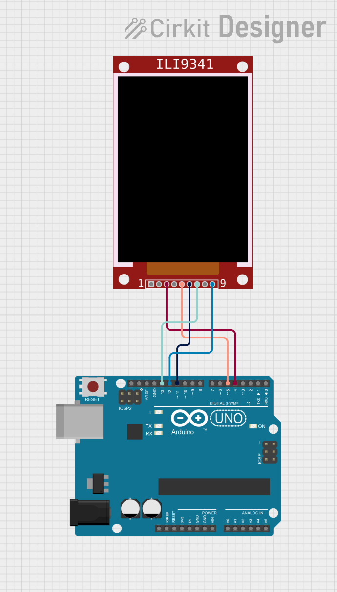
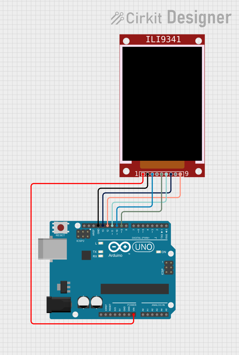
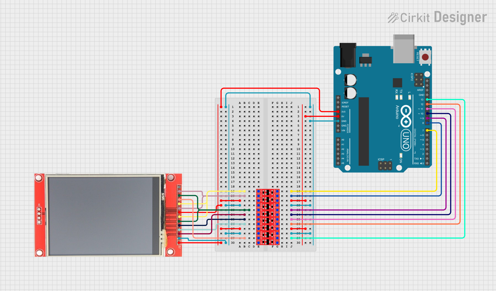
Explore Projects Built with ILI
Common Applications and Use Cases
- Communication between microcontrollers and sensors (e.g., temperature, pressure, or light sensors)
- Interfacing with EEPROMs, ADCs, and DACs
- Connecting real-time clocks (RTC) to microcontrollers
- Driving small displays or other peripherals
- Multi-device communication in embedded systems
Technical Specifications
Key Technical Details
- Protocol Type: Serial, synchronous
- Number of Wires: 2 (SDA - Serial Data, SCL - Serial Clock)
- Data Transfer Rate: Standard mode (100 kHz), Fast mode (400 kHz), Fast mode plus (1 MHz), High-speed mode (3.4 MHz)
- Addressing: 7-bit or 10-bit addressing
- Maximum Devices: Up to 127 devices (7-bit addressing)
- Voltage Levels: Typically 3.3V or 5V (depending on the system)
- Pull-up Resistors: Required on both SDA and SCL lines
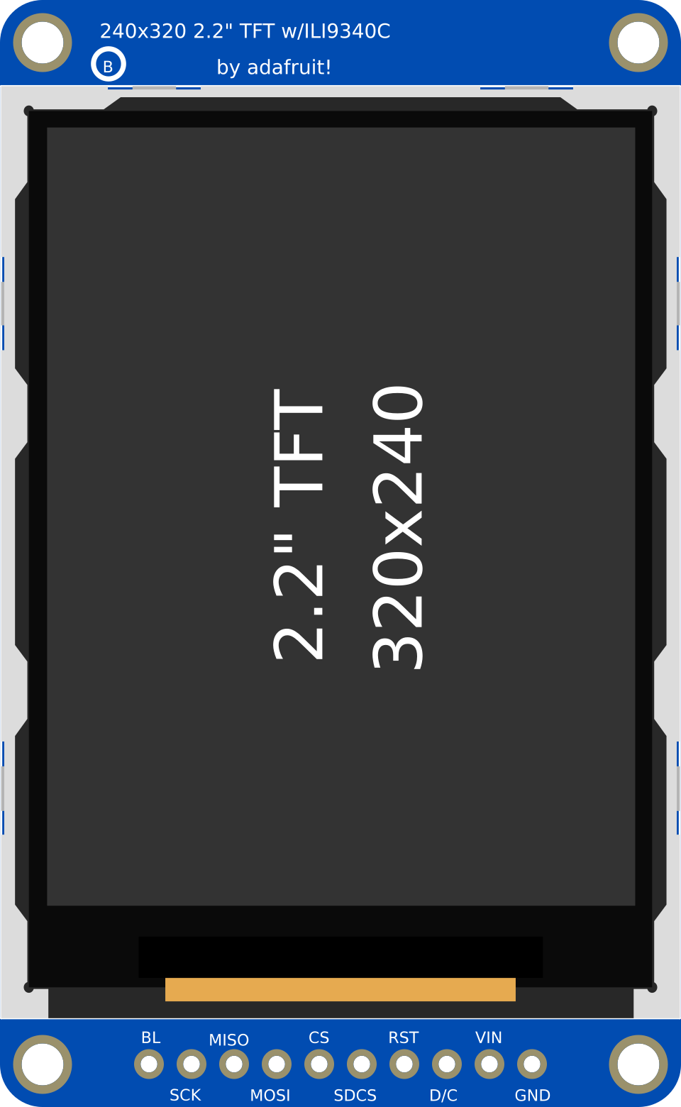
Pin Configuration and Descriptions
The ILI protocol does not refer to a specific physical component but rather a communication standard. However, devices using ILI typically have the following pin configuration:
| Pin Name | Description |
|---|---|
| SDA | Serial Data Line: Used for bidirectional data transfer between devices. |
| SCL | Serial Clock Line: Provides the clock signal for synchronizing data transfer. |
| GND | Ground: Common ground connection for all devices on the ILI bus. |
| VCC | Power Supply: Provides power to the device (e.g., 3.3V or 5V). |
Usage Instructions
How to Use the Component in a Circuit
Connect the SDA and SCL Lines:
- Connect the SDA and SCL pins of all devices to the corresponding lines on the ILI bus.
- Use pull-up resistors (typically 4.7 kΩ or 10 kΩ) on both SDA and SCL lines to ensure proper signal levels.
Power the Devices:
- Connect the VCC and GND pins of all devices to the appropriate power supply and ground.
Assign Unique Addresses:
- Ensure each device on the ILI bus has a unique address. This is typically set by hardware (e.g., address pins) or software.
Write Code for Communication:
- Use a microcontroller or processor to send and receive data over the ILI bus. Libraries like
Wire.h(for Arduino) simplify this process.
- Use a microcontroller or processor to send and receive data over the ILI bus. Libraries like
Important Considerations and Best Practices
- Pull-up Resistors: Always include pull-up resistors on the SDA and SCL lines. Without them, the bus will not function correctly.
- Bus Length: Keep the bus length as short as possible to minimize signal degradation and interference.
- Clock Speed: Ensure all devices on the bus support the selected clock speed.
- Address Conflicts: Avoid address conflicts by verifying the unique address of each device.
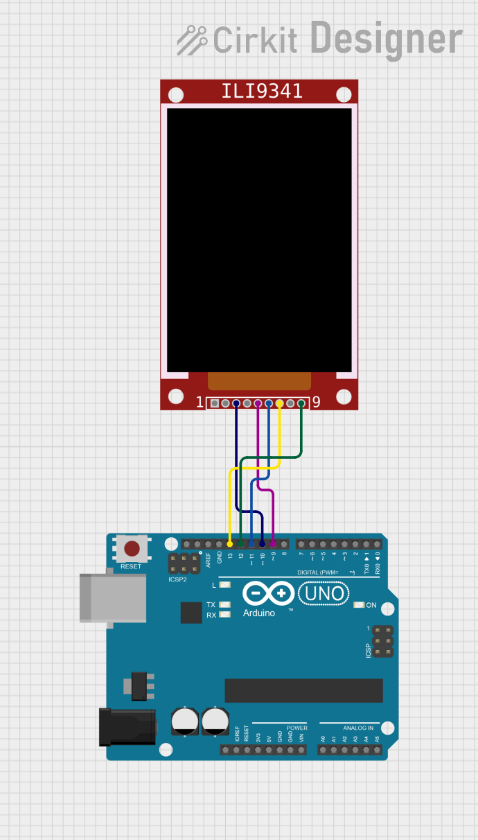
Example Code for Arduino UNO
Below is an example of how to use the ILI protocol to communicate with a sensor using an Arduino UNO:
#include <Wire.h> // Include the Wire library for ILI communication

#define SENSOR_ADDRESS 0x40 // Replace with the ILI address of your sensor

void setup() {
  Wire.begin(); // Initialize the ILI bus
  Serial.begin(9600); // Start serial communication for debugging
}

void loop() {
  Wire.beginTransmission(SENSOR_ADDRESS); // Start communication with the sensor
  Wire.write(0x00); // Send a command or register address (example: 0x00)
  Wire.endTransmission(); // End the transmission

  Wire.requestFrom(SENSOR_ADDRESS, 2); // Request 2 bytes of data from the sensor
  if (Wire.available() == 2) { // Check if 2 bytes are available
    int data = Wire.read() << 8 | Wire.read(); // Read and combine the 2 bytes
    Serial.println(data); // Print the received data to the serial monitor
  }

  delay(1000); // Wait for 1 second before the next communication
}
Troubleshooting and FAQs
Common Issues and Solutions
No Communication on the Bus:
- Cause: Missing or incorrect pull-up resistors.
- Solution: Ensure pull-up resistors are connected to both SDA and SCL lines.
Address Conflicts:
- Cause: Two devices on the bus have the same address.
- Solution: Check the datasheets of the devices and configure unique addresses.
Data Corruption:
- Cause: Excessive bus length or noise.
- Solution: Shorten the bus length and use shielded cables if necessary.
Device Not Responding:
- Cause: Incorrect wiring or power supply issues.
- Solution: Double-check all connections and ensure proper power supply.
FAQs
Q: Can I connect devices with different voltage levels on the same ILI bus?
A: Yes, but you will need a level shifter to safely interface devices with different voltage levels.Q: What happens if I forget to add pull-up resistors?
A: The ILI bus will not function correctly, as the lines will not return to a high state.Q: How many devices can I connect to the ILI bus?
A: Up to 127 devices can be connected using 7-bit addressing, but practical limits depend on bus capacitance and signal integrity.Q: Can I use ILI for long-distance communication?
A: ILI is not designed for long distances. For longer distances, consider using protocols like RS-485 or CAN.
This documentation provides a comprehensive guide to understanding and using the ILI protocol in your projects.