Cirkit Designer Logo
Cirkit Designer
Your all-in-one circuit design IDE
Home / 
Component Documentation

How to Use SparkFun RedBoard Qwiic: Examples, Pinouts, and Specs

Image of SparkFun RedBoard Qwiic
Cirkit Designer LogoDesign with SparkFun RedBoard Qwiic in Cirkit Designer

Introduction

The SparkFun RedBoard Qwiic is an Arduino-compatible development board that simplifies the process of prototyping and building electronic projects. It is based on the popular ATmega328P microcontroller and is fully compatible with the Arduino IDE. The board's standout feature is its Qwiic connect system, which allows for easy daisy-chaining of I2C devices without the need for soldering. This makes it an ideal platform for rapid development and educational purposes, as well as for hobbyists and professionals looking to streamline their I2C-based projects.

Explore Projects Built with SparkFun RedBoard Qwiic

Use Cirkit Designer to design, explore, and prototype these projects online. Some projects support real-time simulation. Click "Open Project" to start designing instantly!
SparkFun RedBoard Controlled Multi-Servo Circuit
Image of Sassy-Display: A project utilizing SparkFun RedBoard Qwiic in a practical application
This circuit consists of a SparkFun RedBoard, which is an Arduino-compatible development platform, connected to four servo motors. The RedBoard provides 5V power and ground to each servo, and it also controls the servos using PWM signals on pins D3, D4, D5, and D6. The purpose of this circuit is to independently control the position or speed of four servos, commonly used in robotics and RC applications.
Cirkit Designer LogoOpen Project in Cirkit Designer
Battery-Powered Smart Light with Proximity Sensor and OLED Display using Adafruit QT Py RP2040
Image of lab: A project utilizing SparkFun RedBoard Qwiic in a practical application
This circuit is a portable, battery-powered system featuring an Adafruit QT Py RP2040 microcontroller that interfaces with an OLED display, a proximity sensor, an accelerometer, and an RGB LED strip. The system is powered by a lithium-ion battery with a step-up boost converter to provide 5V for the LED strip, and it includes a toggle switch for power control. The microcontroller communicates with the sensors and display via I2C.
Cirkit Designer LogoOpen Project in Cirkit Designer
Battery-Powered Sensor Hub with Adafruit QT Py RP2040 and OLED Display
Image of 512: A project utilizing SparkFun RedBoard Qwiic in a practical application
This circuit features an Adafruit QT Py RP2040 microcontroller interfacing with an MPU-6050 accelerometer, an Adafruit APDS-9960 sensor, and a 0.96" OLED display via I2C communication. It is powered by a 3.7V LiPo battery and includes a green LED with a current-limiting resistor connected to an analog pin of the microcontroller.
Cirkit Designer LogoOpen Project in Cirkit Designer
Battery-Powered Smart Sensor Hub with Adafruit QT Py RP2040
Image of wearable final: A project utilizing SparkFun RedBoard Qwiic in a practical application
This circuit features an Adafruit QT Py RP2040 microcontroller interfaced with an APDS9960 proximity sensor, an MPU6050 accelerometer and gyroscope, and an OLED display via I2C communication. It also includes a buzzer controlled by the microcontroller and is powered by a 3.7V LiPo battery with a toggle switch for power control.
Cirkit Designer LogoOpen Project in Cirkit Designer

Explore Projects Built with SparkFun RedBoard Qwiic

Use Cirkit Designer to design, explore, and prototype these projects online. Some projects support real-time simulation. Click "Open Project" to start designing instantly!
Image of Sassy-Display: A project utilizing SparkFun RedBoard Qwiic in a practical application
SparkFun RedBoard Controlled Multi-Servo Circuit
This circuit consists of a SparkFun RedBoard, which is an Arduino-compatible development platform, connected to four servo motors. The RedBoard provides 5V power and ground to each servo, and it also controls the servos using PWM signals on pins D3, D4, D5, and D6. The purpose of this circuit is to independently control the position or speed of four servos, commonly used in robotics and RC applications.
Cirkit Designer LogoOpen Project in Cirkit Designer
Image of lab: A project utilizing SparkFun RedBoard Qwiic in a practical application
Battery-Powered Smart Light with Proximity Sensor and OLED Display using Adafruit QT Py RP2040
This circuit is a portable, battery-powered system featuring an Adafruit QT Py RP2040 microcontroller that interfaces with an OLED display, a proximity sensor, an accelerometer, and an RGB LED strip. The system is powered by a lithium-ion battery with a step-up boost converter to provide 5V for the LED strip, and it includes a toggle switch for power control. The microcontroller communicates with the sensors and display via I2C.
Cirkit Designer LogoOpen Project in Cirkit Designer
Image of 512: A project utilizing SparkFun RedBoard Qwiic in a practical application
Battery-Powered Sensor Hub with Adafruit QT Py RP2040 and OLED Display
This circuit features an Adafruit QT Py RP2040 microcontroller interfacing with an MPU-6050 accelerometer, an Adafruit APDS-9960 sensor, and a 0.96" OLED display via I2C communication. It is powered by a 3.7V LiPo battery and includes a green LED with a current-limiting resistor connected to an analog pin of the microcontroller.
Cirkit Designer LogoOpen Project in Cirkit Designer
Image of wearable final: A project utilizing SparkFun RedBoard Qwiic in a practical application
Battery-Powered Smart Sensor Hub with Adafruit QT Py RP2040
This circuit features an Adafruit QT Py RP2040 microcontroller interfaced with an APDS9960 proximity sensor, an MPU6050 accelerometer and gyroscope, and an OLED display via I2C communication. It also includes a buzzer controlled by the microcontroller and is powered by a 3.7V LiPo battery with a toggle switch for power control.
Cirkit Designer LogoOpen Project in Cirkit Designer

Common Applications and Use Cases

  • Rapid prototyping of microcontroller-based projects
  • Educational platforms for teaching electronics and programming
  • I2C sensor integration and data logging
  • DIY electronics and robotics
  • Interactive art installations

Technical Specifications

Key Technical Details

  • Microcontroller: ATmega328P
  • Operating Voltage: 5V
  • Input Voltage: 7-15V
  • Digital I/O Pins: 14 (of which 6 provide PWM output)
  • Analog Input Pins: 6
  • DC Current per I/O Pin: 40 mA
  • DC Current for 3.3V Pin: 150 mA
  • Flash Memory: 32 KB (ATmega328P) of which 0.5 KB used by bootloader
  • SRAM: 2 KB (ATmega328P)
  • EEPROM: 1 KB (ATmega328P)
  • Clock Speed: 16 MHz
  • Qwiic Connect System: 2x connectors for I2C devices

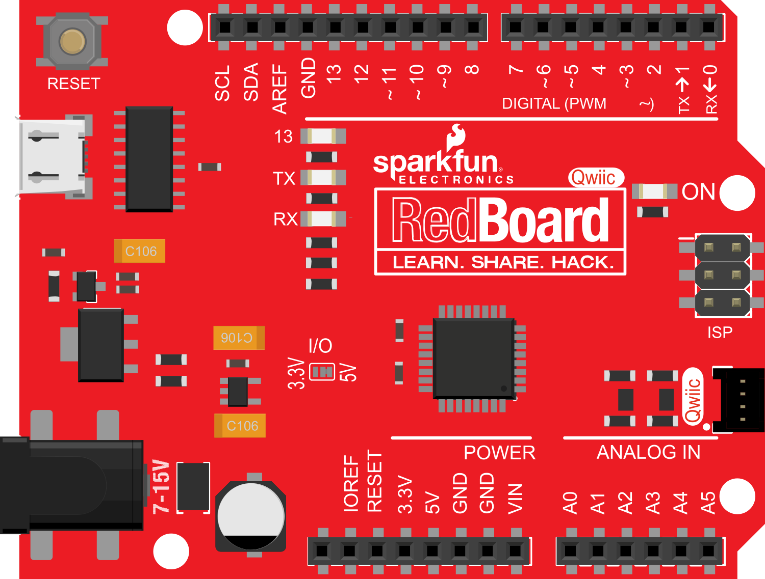
Pin Configuration and Descriptions

Pin Number Function Description
1 RESET Resets the microcontroller
2-13 Digital I/O Digital input/output pins, PWM on 3, 5, 6, 9, 10, 11
14-19 Analog Input Analog input pins (A0-A5)
20, 21 I2C / TWI SDA (data line) and SCL (clock line) for I2C communication
AREF Analog Reference Reference voltage for the analog inputs
GND Ground Common ground for circuits
VIN Voltage Input Input voltage to the board (7-15V)
5V 5V Output Regulated 5V output
3.3V 3.3V Output Regulated 3.3V output

Usage Instructions

How to Use the Component in a Circuit

  1. Powering the Board:

    • Connect a 7-15V power supply to the VIN and GND pins, or plug in the board via the USB connection to power it from your computer.
  2. Connecting I2C Devices:

    • Use the Qwiic connectors to daisy-chain I2C devices. Ensure that each device has a unique I2C address to avoid conflicts.
  3. Programming the Board:

    • Connect the board to your computer using a USB cable.
    • Open the Arduino IDE, select the correct board (Arduino UNO) and port.
    • Write or load your sketch (program) and upload it to the board.

Important Considerations and Best Practices

  • Always disconnect the board from power sources before making or altering connections.
  • Observe proper polarity for power connections to prevent damage.
  • Avoid drawing more than 40 mA from any single I/O pin.
  • When using PWM, remember that the analogWrite function does not output true analog signals but rather a square wave of varying pulse width.

Troubleshooting and FAQs

Common Issues Users Might Face

  • Board not recognized by computer:
    • Ensure the USB cable is properly connected and the correct drivers are installed.
  • I2C device not working:
    • Check that the device is correctly connected to the Qwiic system and that there are no address conflicts.

Solutions and Tips for Troubleshooting

  • If the board is not recognized, try a different USB cable or port, and ensure that the board is selected in the Arduino IDE.
  • For I2C issues, use the I2C scanner sketch to verify that the device is detected on the bus.

FAQs

  • Can I power the board with more than 15V?
    • No, exceeding the recommended voltage can damage the board.
  • How many I2C devices can I connect?
    • This depends on the number of unique addresses available for your devices. The Qwiic system supports chaining multiple devices as long as address conflicts are avoided.

Example Code for Arduino UNO

Here is a simple example of how to blink an LED on pin 13 of the SparkFun RedBoard Qwiic:

// Define the LED pin
const int ledPin = 13;

// the setup routine runs once when you press reset:
void setup() {
  // initialize the digital pin as an output.
  pinMode(ledPin, OUTPUT);
}

// the loop routine runs over and over again forever:
void loop() {
  digitalWrite(ledPin, HIGH);   // turn the LED on (HIGH is the voltage level)
  delay(1000);                  // wait for a second
  digitalWrite(ledPin, LOW);    // turn the LED off by making the voltage LOW
  delay(1000);                  // wait for a second
}

Remember to keep your code comments concise and within the 80 character line length limit. This example demonstrates the basic structure of an Arduino sketch, including setup and loop functions, and controlling a digital output.