How to Use Arduino GIGA R1: Examples, Pinouts, and Specs
Introduction
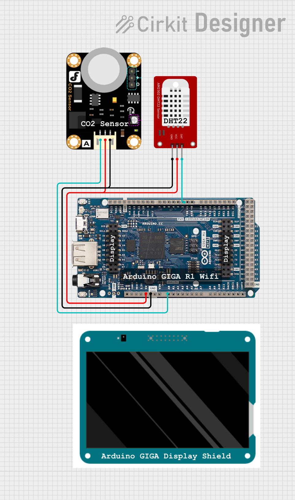
The Arduino GIGA R1 WiFi is a high-performance microcontroller board designed for advanced projects requiring significant processing power and connectivity. It features a dual-core ARM Cortex-M7 and Cortex-M4 architecture, making it ideal for applications such as robotics, IoT, machine learning, and multimedia processing. With its extensive GPIO pins, built-in WiFi and Bluetooth capabilities, and compatibility with a wide range of sensors and modules, the GIGA R1 is a versatile tool for both hobbyists and professionals.
Explore Projects Built with Arduino GIGA R1
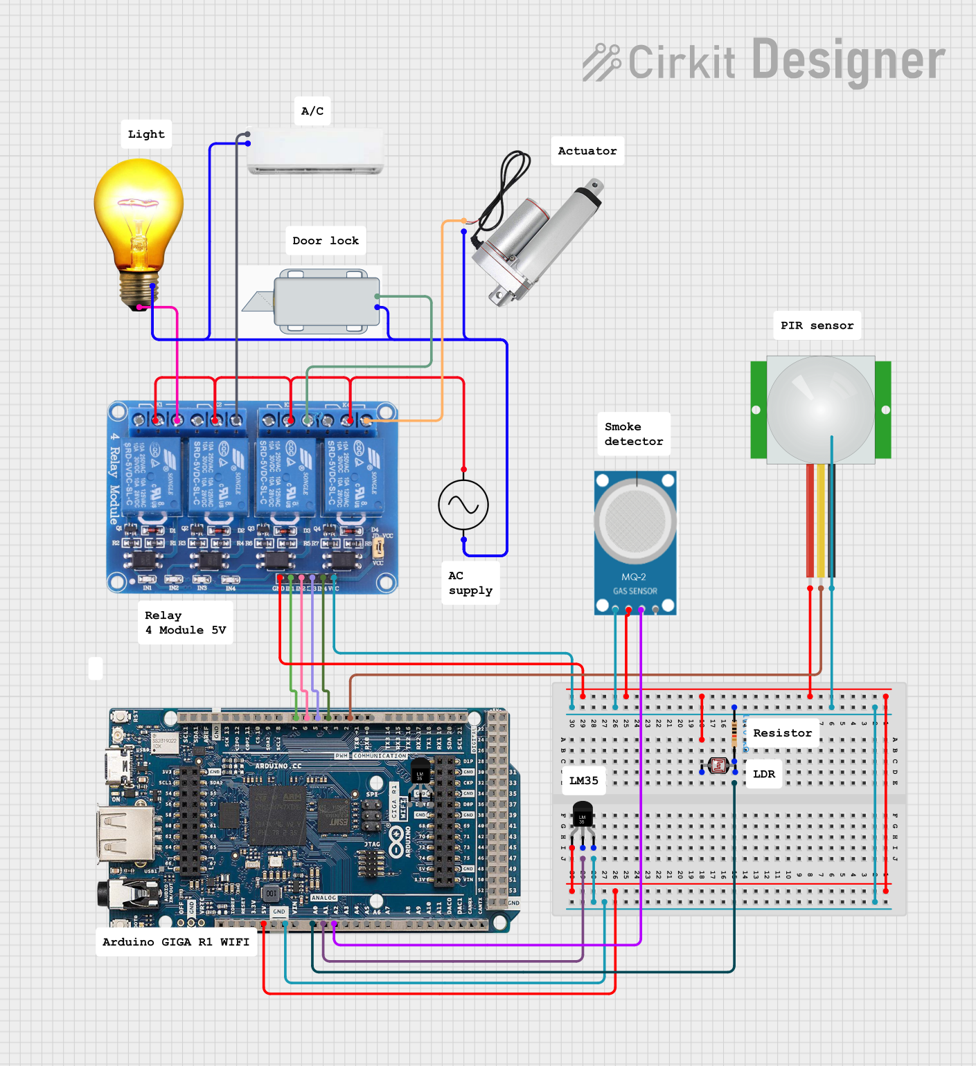
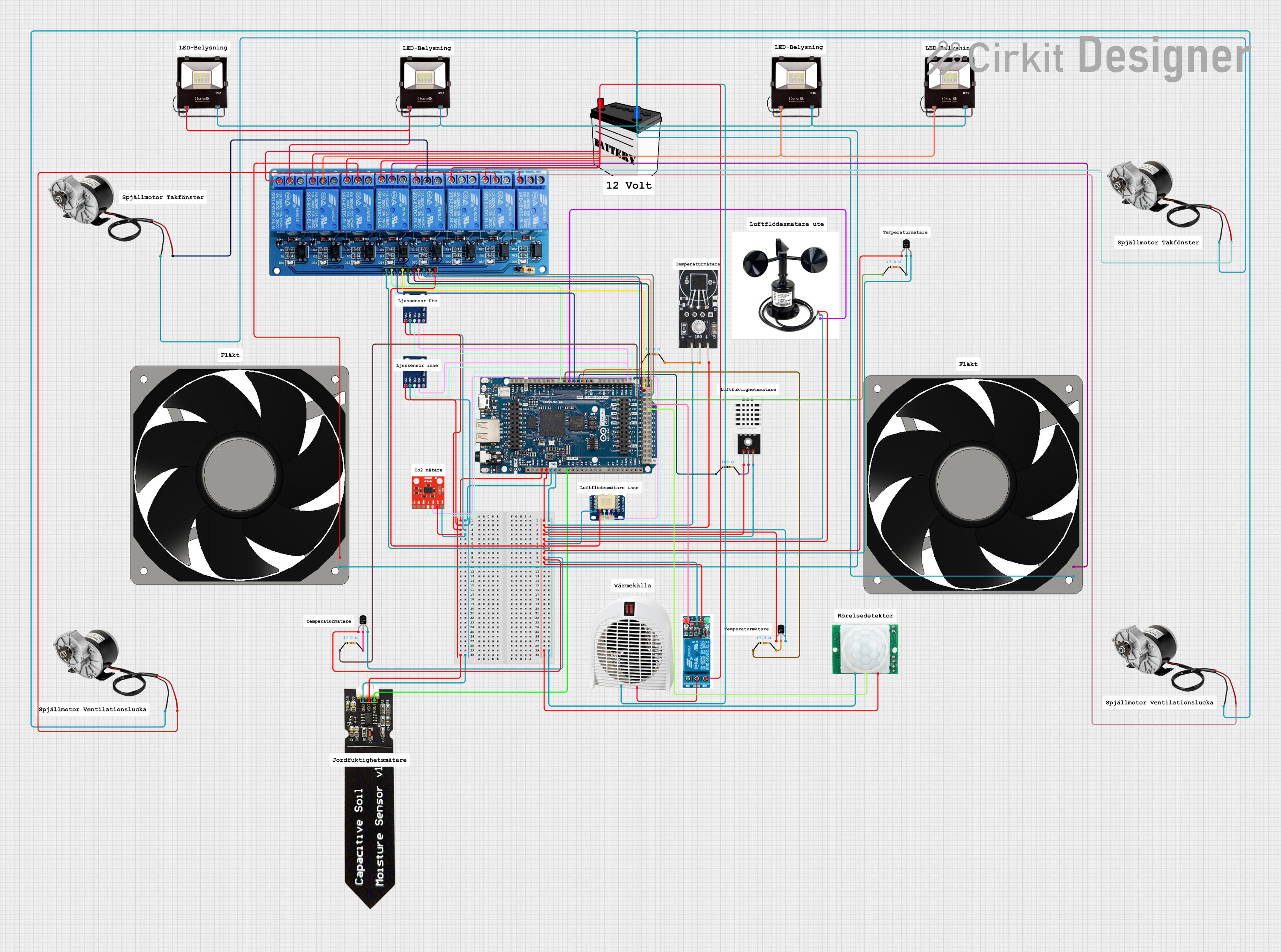
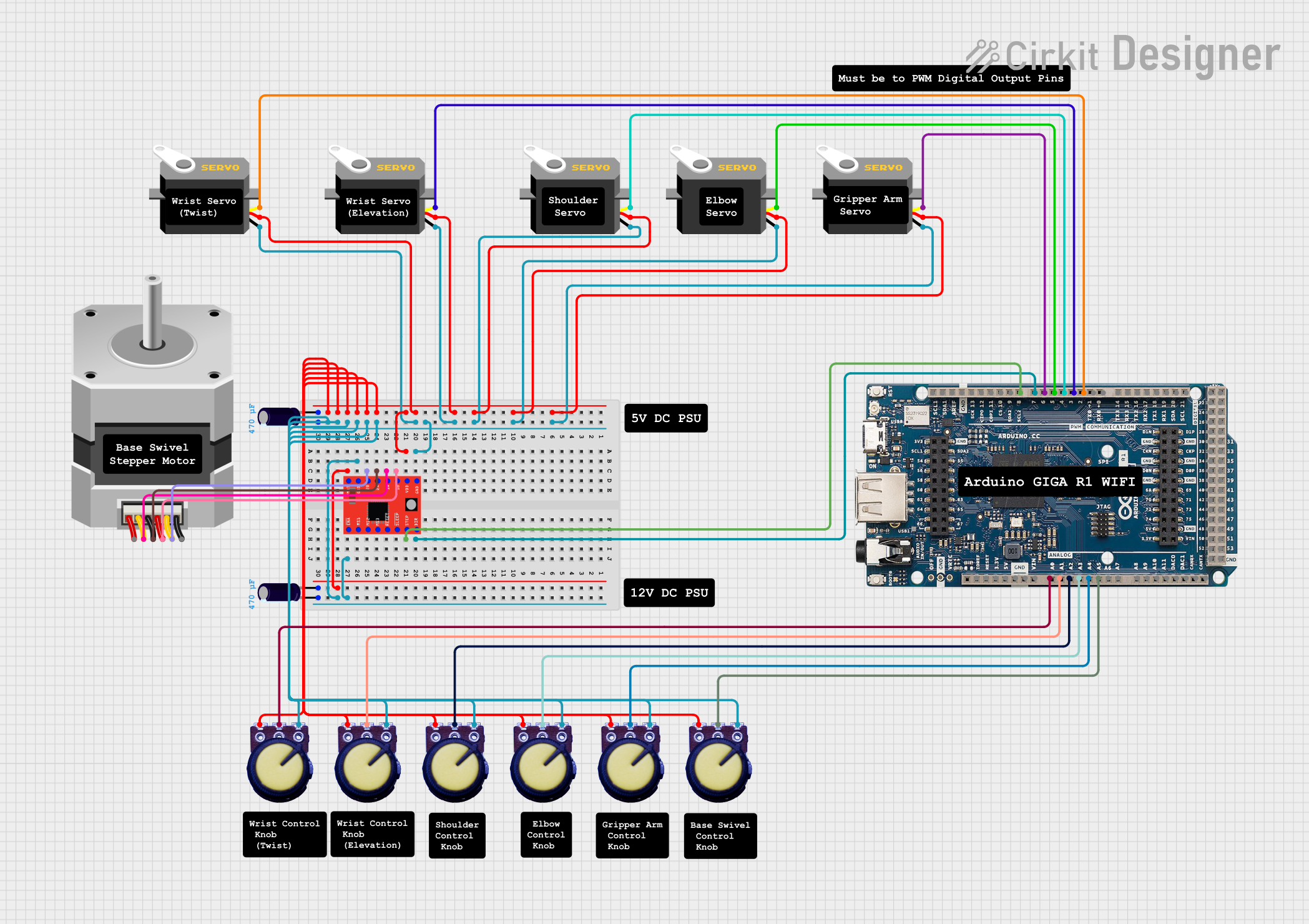
Explore Projects Built with Arduino GIGA R1
Common Applications
- Robotics and automation systems
- IoT (Internet of Things) devices
- Machine learning and AI-based projects
- Multimedia processing (e.g., audio and video)
- Data acquisition and real-time monitoring
- Advanced prototyping and research projects
Technical Specifications
Key Technical Details
| Specification | Value |
|---|---|
| Microcontroller | Dual-core ARM Cortex-M7 (480 MHz) and Cortex-M4 (240 MHz) |
| Operating Voltage | 3.3V |
| Input Voltage (VIN) | 7-12V |
| Digital I/O Pins | 76 (12 PWM outputs) |
| Analog Input Pins | 12 (ADC resolution: 12-bit) |
| Analog Output Pins | 2 (DAC resolution: 12-bit) |
| Flash Memory | 16 MB |
| SRAM | 1 MB |
| Connectivity | WiFi, Bluetooth, USB-C, CAN bus, UART, SPI, I2C |
| Power Consumption | ~1.5W (varies based on usage) |
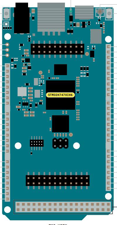
| Dimensions | 102 x 25 mm |
Pin Configuration and Descriptions
The Arduino GIGA R1 WiFi features a rich set of pins for various functionalities. Below is a summary of the pin configuration:
Digital and Analog Pins
| Pin Number | Type | Description |
|---|---|---|
| D0-D53 | Digital I/O | General-purpose digital input/output pins |
| A0-A11 | Analog Input | Analog input pins with 12-bit resolution |
| DAC0, DAC1 | Analog Output | Digital-to-analog converter pins (12-bit) |
Communication Pins
| Pin Number | Type | Description |
|---|---|---|
| TX/RX | UART | Serial communication pins |
| SDA/SCL | I2C | I2C communication pins |
| MOSI/MISO/SCK | SPI | SPI communication pins |
| CANRX/CANTX | CAN Bus | Controller Area Network communication pins |
Power Pins
| Pin Number | Type | Description |
|---|---|---|
| VIN | Power Input | External power input (7-12V) |
| 3.3V | Power Output | 3.3V regulated output |
| 5V | Power Output | 5V regulated output |
| GND | Ground | Ground pins |
Usage Instructions
How to Use the Arduino GIGA R1 in a Circuit
Powering the Board:
- Connect the board to a computer via the USB-C port for programming and power.
- Alternatively, supply external power (7-12V) through the VIN pin or barrel jack.
Programming the Board:
- Install the Arduino IDE (version 2.0 or later) and add the GIGA R1 board via the Boards Manager.
- Select the appropriate port and board type in the IDE.
- Write your code and upload it to the board.
Connecting Peripherals:
- Use the GPIO pins for connecting sensors, actuators, and other modules.
- Ensure proper voltage levels (3.3V logic) to avoid damaging the board.
Using WiFi and Bluetooth:
- The GIGA R1 includes built-in WiFi and Bluetooth modules. Use the
WiFiandBluetoothSeriallibraries in the Arduino IDE to configure and manage wireless communication.
- The GIGA R1 includes built-in WiFi and Bluetooth modules. Use the
Example: Blinking an LED
Here’s a simple example to blink an LED connected to pin D13:
// Define the LED pin
const int ledPin = 13;

void setup() {
  // Set the LED pin as an output
  pinMode(ledPin, OUTPUT);
}

void loop() {
  // Turn the LED on
  digitalWrite(ledPin, HIGH);
  delay(1000); // Wait for 1 second

  // Turn the LED off
  digitalWrite(ledPin, LOW);
  delay(1000); // Wait for 1 second
}
Example: Connecting to WiFi
Below is an example of connecting the GIGA R1 to a WiFi network:
#include <WiFi.h>

// Replace with your network credentials
const char* ssid = "Your_SSID";
const char* password = "Your_PASSWORD";

void setup() {
  // Start the serial communication
  Serial.begin(115200);

  // Connect to WiFi
  Serial.print("Connecting to WiFi...");
  WiFi.begin(ssid, password);

  while (WiFi.status() != WL_CONNECTED) {
    delay(500);
    Serial.print(".");
  }

  // Print the IP address once connected
  Serial.println("\nWiFi connected!");
  Serial.print("IP Address: ");
  Serial.println(WiFi.localIP());
}

void loop() {
  // Add your main code here
}
Important Considerations
- Voltage Levels: The GIGA R1 operates at 3.3V logic. Avoid connecting 5V signals directly to the pins.
- Power Supply: Ensure a stable power supply, especially when using peripherals that draw significant current.
- Dual-Core Programming: Utilize the dual-core architecture for parallel processing. Refer to the official documentation for advanced examples.
Troubleshooting and FAQs
Common Issues and Solutions
The board is not detected by the Arduino IDE:
- Ensure the correct USB-C cable is used (data-capable, not just for charging).
- Verify that the GIGA R1 board is selected in the Boards Manager.
- Check the device manager (Windows) or
ls /dev/tty*(Linux/Mac) for the correct port.
WiFi connection fails:
- Double-check the SSID and password.
- Ensure the WiFi network is within range and operational.
- Restart the board and try reconnecting.
Program upload fails:
- Press the reset button on the board and try uploading again.
- Check for conflicting serial connections or open serial monitors.
Peripherals not working as expected:
- Verify the wiring and connections.
- Ensure the peripherals are compatible with 3.3V logic.
FAQs
Q: Can I use the GIGA R1 with 5V sensors?
A: Yes, but you’ll need a level shifter to safely interface 5V sensors with the 3.3V logic of the GIGA R1.
Q: How do I use both cores of the microcontroller?
A: The Arduino IDE provides libraries and examples for dual-core programming. Refer to the official documentation for details.
Q: Is the GIGA R1 compatible with Arduino shields?
A: Yes, the GIGA R1 is compatible with most Arduino shields, but ensure they support 3.3V logic.
Q: Can I power the board using a LiPo battery?
A: Yes, you can use a LiPo battery with a suitable voltage regulator to provide 7-12V to the VIN pin.
This concludes the documentation for the Arduino GIGA R1 WiFi. For more advanced examples and support, refer to the official Arduino website.