How to Use KY-037: Examples, Pinouts, and Specs
Introduction
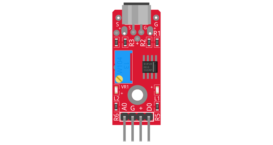
The KY-037 is a sound sensor module designed to detect sound levels and convert them into an analog voltage output. It features a high-sensitivity microphone and an onboard potentiometer for adjusting the sensitivity. The module provides both analog and digital outputs, making it versatile for a wide range of applications.
Explore Projects Built with KY-037

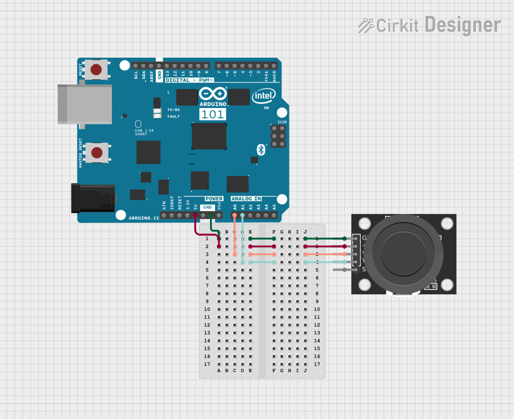
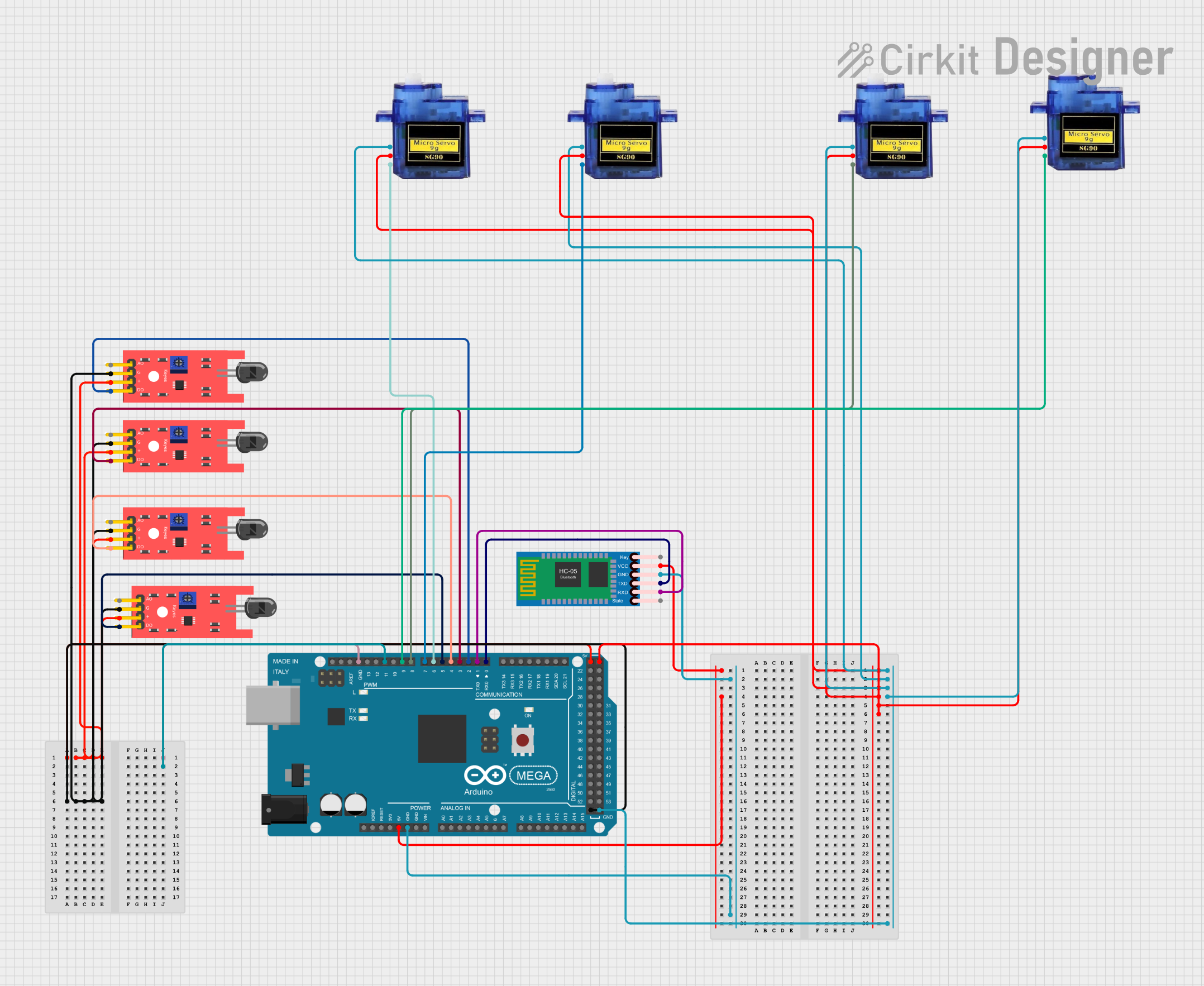

Explore Projects Built with KY-037
Common Applications and Use Cases
- Sound-activated switches
- Audio level monitoring
- Voice-activated systems
- Environmental noise detection
- DIY electronics and Arduino projects
Technical Specifications
The KY-037 sound sensor module has the following key specifications:
| Parameter | Value |
|---|---|
| Operating Voltage | 3.3V - 5V |
| Output Types | Analog (A0) and Digital (D0) |
| Microphone Type | Electret Condenser Microphone |
| Sensitivity Adjustment | Onboard potentiometer |
| Dimensions | 38mm x 15mm x 13mm |
Pin Configuration and Descriptions
The KY-037 module has four pins, as described in the table below:
| Pin | Label | Description |
|---|---|---|
| 1 | VCC | Power supply pin. Connect to 3.3V or 5V. |
| 2 | GND | Ground pin. Connect to the ground of the circuit. |
| 3 | A0 | Analog output pin. Outputs a voltage proportional to the detected sound level. |
| 4 | D0 | Digital output pin. Outputs HIGH or LOW based on the sound threshold set by the potentiometer. |
Usage Instructions
How to Use the KY-037 in a Circuit
- Power the Module: Connect the
VCCpin to a 3.3V or 5V power source and theGNDpin to the ground. - Connect Outputs:
- For analog sound level readings, connect the
A0pin to an analog input pin on your microcontroller. - For digital sound detection, connect the
D0pin to a digital input pin on your microcontroller.
- For analog sound level readings, connect the
- Adjust Sensitivity: Use the onboard potentiometer to set the desired sound threshold for the digital output (
D0).
Important Considerations and Best Practices
- Power Supply: Ensure the module is powered within its operating voltage range (3.3V - 5V).
- Noise Interference: Place the module away from sources of electrical noise to avoid false readings.
- Sensitivity Adjustment: Fine-tune the potentiometer to achieve the desired sensitivity for your application.
- Analog vs. Digital Output: Use the analog output (
A0) for precise sound level measurements and the digital output (D0) for simple sound detection.
Example: Connecting KY-037 to an Arduino UNO
Below is an example of how to use the KY-037 with an Arduino UNO to read both analog and digital outputs:
// KY-037 Sound Sensor Example with Arduino UNO
// Reads analog sound levels and detects sound using the digital output

// Define pin connections
const int analogPin = A0;  // KY-037 A0 connected to Arduino A0
const int digitalPin = 2;  // KY-037 D0 connected to Arduino digital pin 2
const int ledPin = 13;     // Built-in LED for sound detection feedback

void setup() {
  pinMode(digitalPin, INPUT);  // Set digital pin as input
  pinMode(ledPin, OUTPUT);     // Set LED pin as output
  Serial.begin(9600);          // Initialize serial communication
}

void loop() {
  // Read analog sound level
  int soundLevel = analogRead(analogPin);
  Serial.print("Analog Sound Level: ");
  Serial.println(soundLevel);

  // Check digital sound detection
  if (digitalRead(digitalPin) == HIGH) {
    digitalWrite(ledPin, HIGH);  // Turn on LED if sound is detected
    Serial.println("Sound Detected!");
  } else {
    digitalWrite(ledPin, LOW);   // Turn off LED if no sound is detected
  }

  delay(100);  // Small delay for stability
}
Troubleshooting and FAQs
Common Issues and Solutions
No Output from the Module:
- Ensure the module is powered correctly (3.3V - 5V).
- Check all connections for loose wires or incorrect pin assignments.
Digital Output Always HIGH or LOW:
- Adjust the sensitivity using the onboard potentiometer.
- Verify that the sound level exceeds the threshold for detection.
Inconsistent Analog Readings:
- Minimize electrical noise by using shorter wires and proper grounding.
- Ensure the microphone is not obstructed or damaged.
Arduino Not Detecting Sound:
- Confirm that the correct pins are defined in the Arduino code.
- Test the module with a multimeter to verify its output.
FAQs
Q: Can the KY-037 detect specific frequencies?
A: No, the KY-037 is not frequency-selective. It detects overall sound levels and cannot differentiate between specific frequencies.
Q: How do I know if the module is working?
A: The onboard LED will light up when the digital output (D0) is HIGH, indicating sound detection.
Q: Can I use the KY-037 with a 3.3V microcontroller?
A: Yes, the KY-037 is compatible with both 3.3V and 5V systems. Ensure the VCC pin is connected to the appropriate voltage.
Q: What is the range of the analog output?
A: The analog output (A0) provides a voltage range from 0V to the supply voltage (3.3V or 5V), proportional to the detected sound level.