How to Use SWITCHING 12V 10A: Examples, Pinouts, and Specs
Introduction
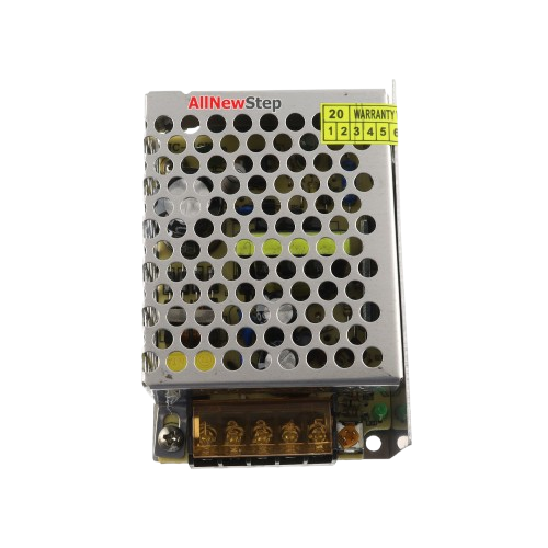
The SWITCHING 12V 10A is a high-efficiency switching power supply designed to convert standard AC mains voltage (typically 110V or 220V) into a stable 12V DC output. It is capable of delivering up to 10A of current, making it suitable for powering a wide range of electronic devices and systems. This power supply is commonly used in applications such as LED lighting, industrial control systems, 3D printers, CCTV systems, and other devices requiring a reliable 12V DC power source.
Explore Projects Built with SWITCHING 12V 10A

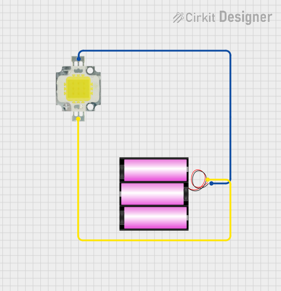
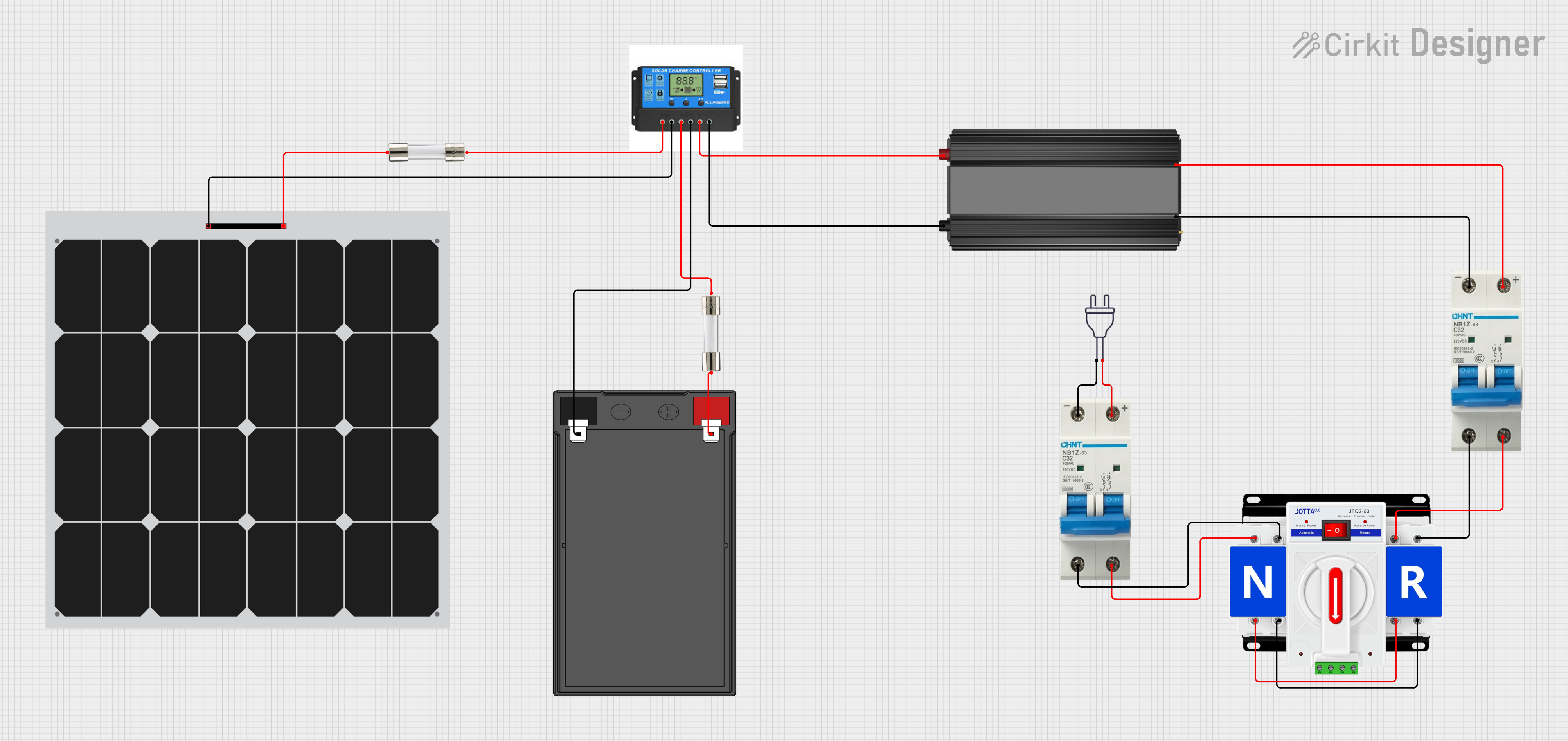
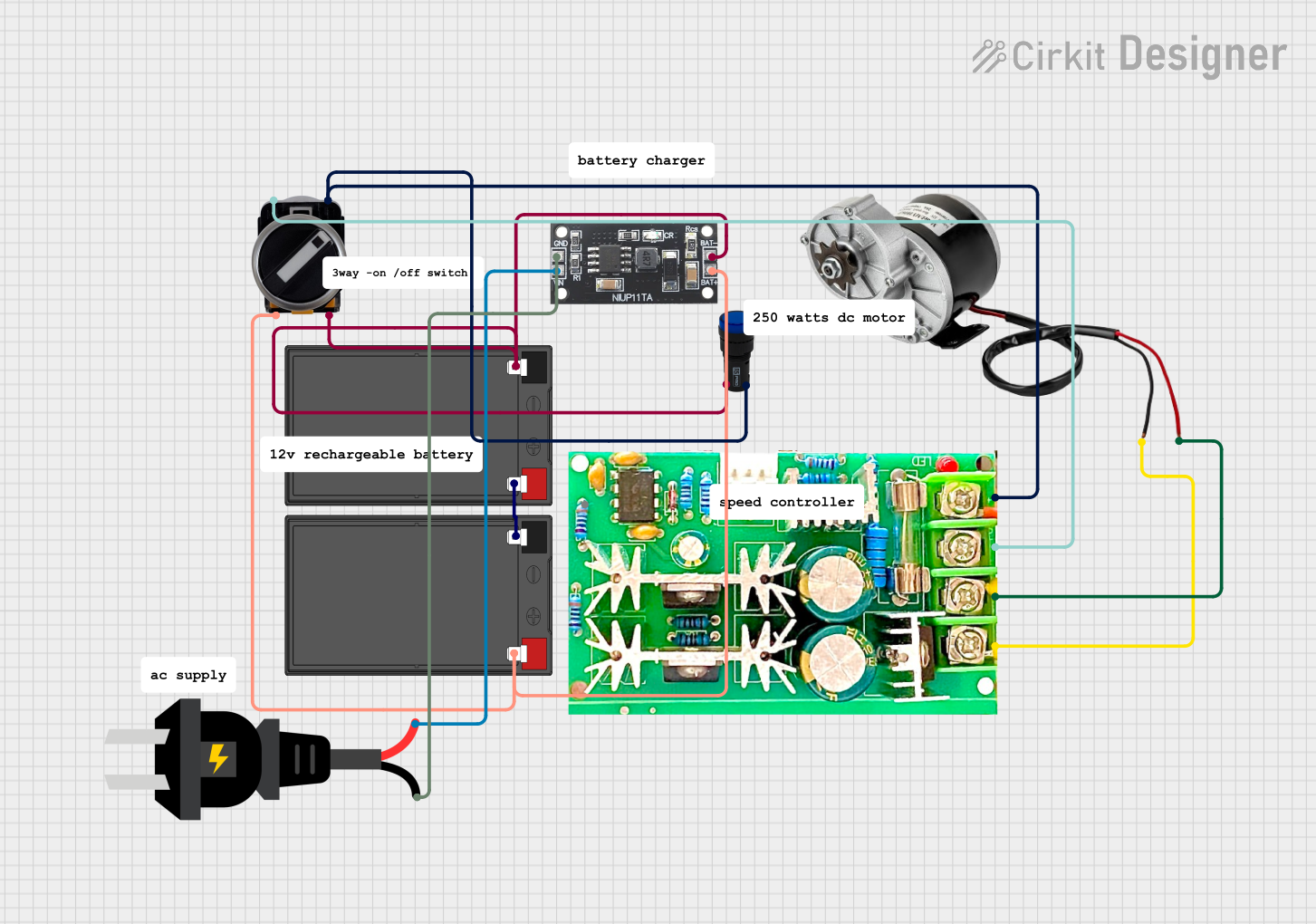
Explore Projects Built with SWITCHING 12V 10A
Technical Specifications
Below are the key technical details of the SWITCHING 12V 10A power supply:
| Parameter | Specification |
|---|---|
| Input Voltage Range | 100V - 240V AC, 50/60Hz |
| Output Voltage | 12V DC |
| Maximum Output Current | 10A |
| Output Power | 120W |
| Efficiency | ≥ 85% |
| Ripple and Noise | ≤ 120mV |
| Operating Temperature | -10°C to +60°C |
| Protection Features | Overload, Overvoltage, Short Circuit |
| Dimensions | Varies by model (e.g., 160mm x 98mm x 42mm) |
| Weight | ~500g |
Pin Configuration and Descriptions
The power supply typically has the following input and output terminals:
Input Terminals
| Pin | Label | Description |
|---|---|---|
| 1 | L | Live AC input (110V/220V) |
| 2 | N | Neutral AC input |
| 3 | GND | Ground (Earth) |
Output Terminals
| Pin | Label | Description |
|---|---|---|
| 1 | V+ | Positive 12V DC output |
| 2 | V+ | Positive 12V DC output (parallel pin) |
| 3 | V- | Negative (GND) DC output |
| 4 | V- | Negative (GND) DC output (parallel pin) |
Usage Instructions
How to Use the Component in a Circuit
- Safety First: Ensure the power supply is disconnected from the mains before wiring.
- Input Connection:
- Connect the AC mains wires to the input terminals (
L,N, andGND). - Use proper insulation and ensure the connections are secure.
- Connect the AC mains wires to the input terminals (
- Output Connection:
- Connect the
V+andV-terminals to your load (e.g., LED strip, motor, or other devices). - Ensure the load does not exceed the maximum current rating of 10A.
- Connect the
- Adjusting Output Voltage (if applicable):
- Some models include a small potentiometer to fine-tune the output voltage. Use a screwdriver to adjust it if needed.
- Power On:
- After verifying all connections, plug the power supply into the mains and switch it on.
Important Considerations and Best Practices
- Load Requirements: Ensure the total load does not exceed 120W (12V x 10A).
- Ventilation: Place the power supply in a well-ventilated area to prevent overheating.
- Protection Features: The power supply includes built-in protections (overload, overvoltage, and short circuit). However, avoid intentionally overloading it.
- Polarity: Double-check the polarity of the output connections to avoid damaging your devices.
- Mounting: Secure the power supply to a stable surface using screws or brackets to prevent movement during operation.
Example: Connecting to an Arduino UNO
The SWITCHING 12V 10A power supply can be used to power an Arduino UNO via a DC-DC step-down converter (buck converter) to reduce the voltage to 5V. Below is an example circuit and code:
Circuit Setup
- Connect the
V+andV-terminals of the power supply to the input of the buck converter. - Adjust the buck converter to output 5V DC.
- Connect the 5V output of the buck converter to the Arduino UNO's
5VandGNDpins.
Example Code
// Example code to blink an LED connected to pin 13 of the Arduino UNO
// Ensure the Arduino is powered via the 5V output of the buck converter

void setup() {
  pinMode(13, OUTPUT); // Set pin 13 as an output pin
}

void loop() {
  digitalWrite(13, HIGH); // Turn the LED on
  delay(1000);            // Wait for 1 second
  digitalWrite(13, LOW);  // Turn the LED off
  delay(1000);            // Wait for 1 second
}
Troubleshooting and FAQs
Common Issues Users Might Face
No Output Voltage:
- Cause: Incorrect wiring or no AC input.
- Solution: Verify the AC input connections and ensure the mains power is on.
Overheating:
- Cause: Insufficient ventilation or excessive load.
- Solution: Ensure proper airflow around the power supply and reduce the load.
Output Voltage Fluctuations:
- Cause: Load exceeding the rated capacity or unstable AC input.
- Solution: Reduce the load or use a voltage stabilizer for the AC input.
Short Circuit Protection Triggered:
- Cause: Output terminals are shorted.
- Solution: Disconnect the power supply, check the wiring, and remove the short circuit.
Solutions and Tips for Troubleshooting
- Use a multimeter to measure the output voltage and verify proper operation.
- If the power supply does not turn on, check the fuse (if accessible) and replace it if blown.
- For persistent issues, consult the manufacturer's documentation or contact technical support.
By following these guidelines, the SWITCHING 12V 10A power supply can be safely and effectively used in a variety of electronic applications.