How to Use NPN Transistor (ECB): Examples, Pinouts, and Specs

Introduction
The NPN transistor is a type of bipolar junction transistor (BJT) that utilizes both electron and hole charge carriers for operation. In the ECB configuration, the three terminals of the transistor are designated as Emitter (E), Collector (C), and Base (B). This configuration allows the emitter to be connected to the collector, enabling the transistor to function as an amplifier or a switch in electronic circuits.
NPN transistors are widely used in various applications, including:
- Signal amplification in audio and RF circuits
- Digital switching in logic circuits
- Motor control and power regulation
- LED driving and other low-power applications
Explore Projects Built with NPN Transistor (ECB)
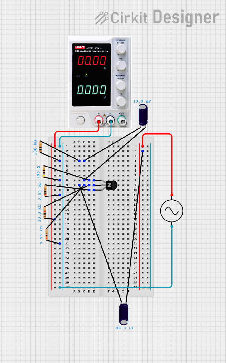

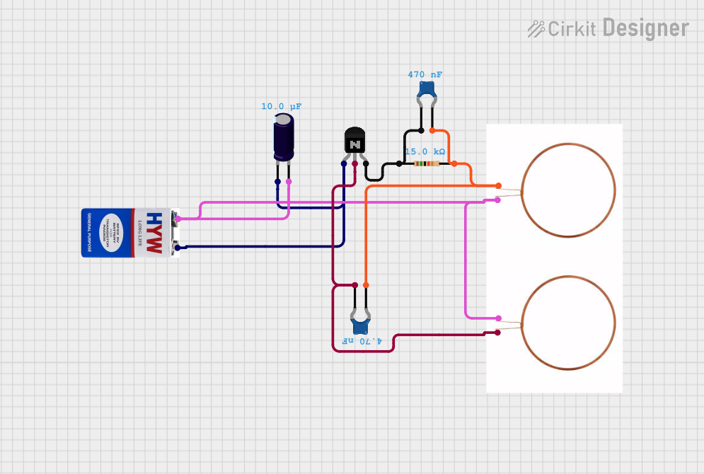
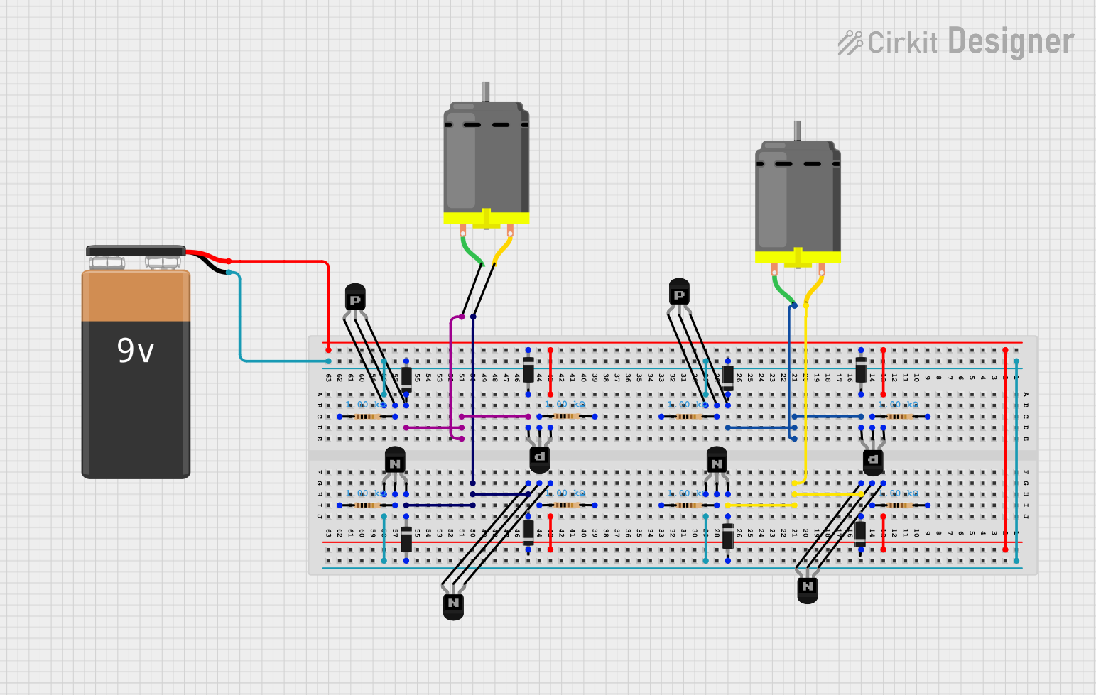
Explore Projects Built with NPN Transistor (ECB)
Technical Specifications
Below are the key technical details for a typical NPN transistor in the ECB configuration. Note that specific values may vary depending on the exact model of the transistor.
General Specifications
- Type: Bipolar Junction Transistor (BJT)
- Configuration: ECB (Emitter-Collector-Base)
- Polarity: NPN
- Maximum Collector-Emitter Voltage (VCE): 40V (typical)
- Maximum Collector Current (IC): 200mA (typical)
- Base-Emitter Voltage (VBE): 0.6V to 0.7V (typical for silicon transistors)
- Power Dissipation (PD): 500mW (typical)
- Gain (hFE): 100 to 300 (varies by model)
Pin Configuration
The pinout for a standard NPN transistor in the ECB configuration is as follows:
| Pin Number | Name | Description |
|---|---|---|
| 1 | Emitter | Emits electrons into the base region |
| 2 | Collector | Collects electrons from the emitter |
| 3 | Base | Controls the flow of current |
Example: TO-92 Package Pinout
For a common TO-92 package, the pinout is typically:
- Emitter (E)
- Collector (C)
- Base (B)
Always refer to the datasheet of your specific transistor model to confirm the pin configuration.
Usage Instructions
How to Use the NPN Transistor in a Circuit
- Identify the Pins: Use the pinout table above or the datasheet to correctly identify the emitter, collector, and base pins.
- Connect the Circuit:
- Connect the emitter to the ground or the negative terminal of the power supply.
- Connect the collector to the load (e.g., an LED or motor) and then to the positive terminal of the power supply.
- Use a resistor to limit the base current and connect the base to the control signal or microcontroller output.
- Apply a Base Current: A small current applied to the base (IB) will control a larger current flowing from the collector to the emitter (IC).
Important Considerations and Best Practices
- Base Resistor: Always use a resistor in series with the base to limit the base current and prevent damage to the transistor.
- Saturation Mode: For switching applications, ensure the transistor is fully saturated by providing sufficient base current (IB ≈ IC / hFE).
- Heat Dissipation: Ensure the transistor does not exceed its maximum power dissipation rating. Use a heatsink if necessary.
- Polarity: Double-check the polarity of the connections to avoid damaging the transistor.
Example: Using an NPN Transistor with Arduino UNO
Below is an example of using an NPN transistor to control an LED with an Arduino UNO.
// Example: Controlling an LED with an NPN Transistor and Arduino UNO
// Transistor: NPN (e.g., 2N2222)
// Pin connections:
// - Emitter (E) to GND
// - Collector (C) to one end of the LED (via a current-limiting resistor)
// - Base (B) to Arduino digital pin (via a base resistor)

const int ledPin = 9;  // Arduino pin connected to the transistor base
const int baseResistor = 1000; // Base resistor value in ohms

void setup() {
  pinMode(ledPin, OUTPUT); // Set the pin as an output
}

void loop() {
  digitalWrite(ledPin, HIGH); // Turn on the LED
  delay(1000);               // Wait for 1 second
  digitalWrite(ledPin, LOW);  // Turn off the LED
  delay(1000);               // Wait for 1 second
}
Note: Ensure the base resistor value is appropriate for the transistor and the Arduino's output voltage (typically 5V).
Troubleshooting and FAQs
Common Issues
Transistor Not Switching:
- Cause: Insufficient base current.
- Solution: Check the base resistor value and ensure it allows enough current to flow into the base.
Overheating:
- Cause: Exceeding the power dissipation rating.
- Solution: Reduce the load current or use a heatsink.
Incorrect Pin Connections:
- Cause: Misidentification of the emitter, collector, and base pins.
- Solution: Double-check the pinout using the datasheet or a multimeter.
LED Not Lighting Up:
- Cause: Incorrect polarity or insufficient current.
- Solution: Verify the LED polarity and ensure the transistor is in saturation mode.
FAQs
Q1: Can I use an NPN transistor to control high-power devices?
A1: Yes, but ensure the transistor's current and voltage ratings are sufficient for the load. For higher power, consider using a power transistor or a relay.
Q2: How do I test if my NPN transistor is working?
A2: Use a multimeter in diode mode to check the base-emitter and base-collector junctions. Both should show a forward voltage drop (~0.6V for silicon transistors).
Q3: What happens if I connect the base directly to a microcontroller pin?
A3: This can damage the microcontroller due to excessive current. Always use a base resistor to limit the current.