
How to Use Adafruit INA169 Analog DC Current Sensor Breakout: Examples, Pinouts, and Specs
 Design with Adafruit INA169 Analog DC Current Sensor Breakout in Cirkit Designer
Introduction
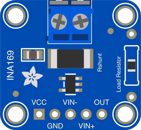
The Adafruit INA169 Analog DC Current Sensor Breakout (Part ID: 1164) is a compact and highly accurate current sensor designed to measure DC current. It features an analog output voltage that is proportional to the current flowing through the sensor, making it easy to integrate into a variety of applications. This breakout board is based on the Texas Instruments INA169 chip, which provides precision current sensing with minimal power loss.
Explore Projects Built with Adafruit INA169 Analog DC Current Sensor Breakout
 Open Project in Cirkit Designer
 Open Project in Cirkit Designer
 Open Project in Cirkit Designer
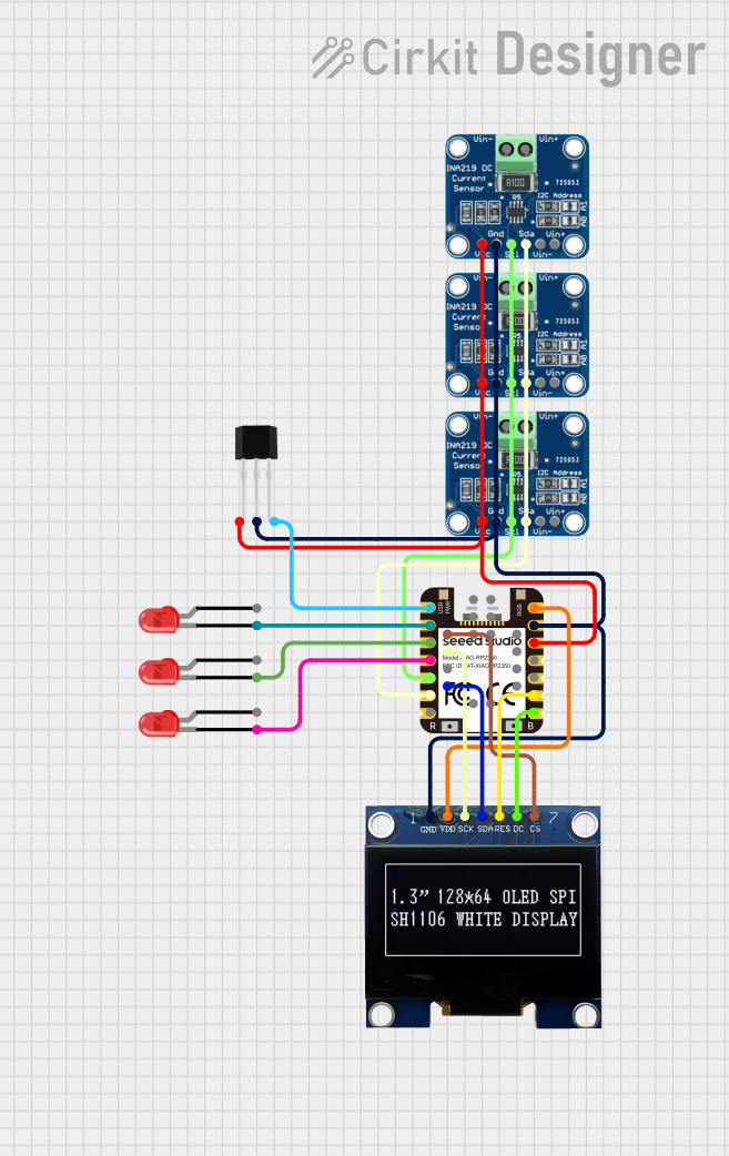 Open Project in Cirkit Designer
Explore Projects Built with Adafruit INA169 Analog DC Current Sensor Breakout
Open Project in Cirkit DesignerOpen Project in Cirkit DesignerOpen Project in Cirkit DesignerOpen Project in Cirkit DesignerCommon Applications and Use Cases
- Battery monitoring in portable devices
- Power management in embedded systems
- Solar panel current measurement
- Motor current sensing in robotics
- General-purpose current sensing in IoT devices
Technical Specifications
The Adafruit INA169 Analog DC Current Sensor Breakout has the following key specifications:
| Parameter | Value |
|---|---|
| Operating Voltage | 2.7V to 60V DC |
| Output Voltage Range | 0V to 3.3V (proportional to current) |
| Maximum Measurable Current | Depends on the shunt resistor (default: 5A) |
| Gain | 1V per 1A (with default 0.1Ω shunt resistor) |
| Accuracy | ±1% typical |
| Operating Temperature Range | -40°C to +125°C |
| Dimensions | 25mm x 20mm x 2mm |
Pin Configuration and Descriptions
The breakout board has 5 pins, as described in the table below:
| Pin Name | Description |
|---|---|
| VIN+ | Positive input for the current to be measured. Connect to the high side of the load. |
| VIN- | Negative input for the current to be measured. Connect to the low side of the load. |
| VOUT | Analog output voltage proportional to the measured current. |
| GND | Ground connection. |
| VCC | Power supply for the INA169 chip (2.7V to 60V). |
Usage Instructions
How to Use the Component in a Circuit
Connect the Power Supply:
- Connect the VCC pin to a power source (2.7V to 60V DC).
- Connect the GND pin to the ground of your circuit.
Connect the Load:
- Connect the VIN+ pin to the positive side of the load.
- Connect the VIN- pin to the negative side of the load.
Read the Output:
- The VOUT pin provides an analog voltage proportional to the current flowing through the load.
- Use an analog-to-digital converter (ADC) or a microcontroller (e.g., Arduino) to read the output voltage.
Calculate the Current:
- The output voltage is proportional to the current based on the formula:
[
I = \frac{V_{OUT}}{R_{SHUNT} \times GAIN}
]
- With the default 0.1Ω shunt resistor and a gain of 1V/A, the current can be calculated as: [ I = V_{OUT} \times 10 ]
- The output voltage is proportional to the current based on the formula:
[
I = \frac{V_{OUT}}{R_{SHUNT} \times GAIN}
]
Important Considerations and Best Practices
- Shunt Resistor Selection: The default shunt resistor is 0.1Ω, which allows for a maximum current of 5A. If you need to measure higher currents, replace the shunt resistor with a lower value.
- Filtering Noise: Add a capacitor (e.g., 0.1µF) across the VOUT pin and GND to filter out noise in the output signal.
- Avoid Overloading: Ensure the current through the shunt resistor does not exceed its power rating to prevent damage.
- Voltage Range: Ensure the voltage across VIN+ and VIN- does not exceed the operating voltage range of the sensor.
Example: Using with Arduino UNO
Below is an example of how to use the Adafruit INA169 with an Arduino UNO to measure current:
// Define the analog pin connected to the VOUT pin of the INA169
const int analogPin = A0;

// Define the shunt resistor value (default: 0.1 ohms)
const float shuntResistor = 0.1;

// Define the gain of the INA169 (default: 1V/A)
const float gain = 1.0;

void setup() {
  Serial.begin(9600); // Initialize serial communication
  Serial.println("Adafruit INA169 Current Sensor Example");
}

void loop() {
  // Read the analog voltage from the INA169
  int sensorValue = analogRead(analogPin);

  // Convert the analog reading to voltage (assuming 5V reference)
  float voltage = sensorValue * (5.0 / 1023.0);

  // Calculate the current in amps
  float current = voltage / (shuntResistor * gain);

  // Print the current to the Serial Monitor
  Serial.print("Current: ");
  Serial.print(current, 3); // Print current with 3 decimal places
  Serial.println(" A");

  delay(1000); // Wait for 1 second before the next reading
}
Troubleshooting and FAQs
Common Issues and Solutions
No Output Voltage on VOUT Pin:
- Cause: Incorrect wiring or no current flowing through the sensor.
- Solution: Double-check the wiring and ensure the load is connected properly.
Output Voltage is Constant or Incorrect:
- Cause: Shunt resistor value does not match the expected value.
- Solution: Verify the shunt resistor value and update your calculations accordingly.
Noise in Output Signal:
- Cause: Electrical noise in the circuit.
- Solution: Add a decoupling capacitor (e.g., 0.1µF) across the VOUT pin and GND.
Overheating of Shunt Resistor:
- Cause: Current exceeds the power rating of the shunt resistor.
- Solution: Use a shunt resistor with a higher power rating or lower resistance.
FAQs
Q: Can the INA169 measure AC current?
A: No, the INA169 is designed for DC current measurement only.
Q: How do I increase the measurable current range?
A: Replace the default 0.1Ω shunt resistor with a lower resistance value. Note that this will reduce the output voltage for a given current.
Q: Can I use the INA169 with a 3.3V microcontroller?
A: Yes, the INA169 is compatible with 3.3V systems. Ensure the VOUT pin voltage does not exceed the ADC input range of your microcontroller.
Q: What is the maximum current the INA169 can measure?
A: The maximum current depends on the shunt resistor value and its power rating. With the default 0.1Ω resistor, the maximum current is 5A.
This concludes the documentation for the Adafruit INA169 Analog DC Current Sensor Breakout.