How to Use 12 to 220: Examples, Pinouts, and Specs
Introduction
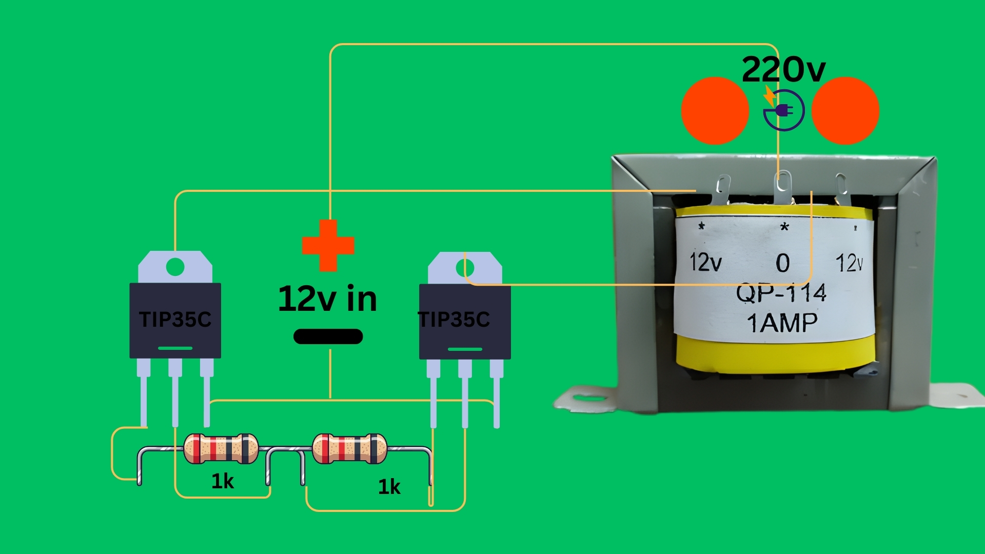
The 12 to 220 voltage converter is an electronic device designed to step up a low DC voltage (12V) to a high AC voltage (220V). This component is widely used in power supply applications, enabling the operation of devices that require 220V AC power from a 12V DC source, such as car batteries or solar power systems. It is a critical component in inverters, portable power systems, and renewable energy setups.
Explore Projects Built with 12 to 220


Explore Projects Built with 12 to 220
Common Applications and Use Cases
- Powering household appliances from a 12V battery in off-grid systems.
- Enabling the use of 220V devices in vehicles or boats.
- Solar energy systems for converting stored DC power to usable AC power.
- Emergency backup power supplies.
Technical Specifications
The following are the key technical details of the 12 to 220 voltage converter:
| Parameter | Value |
|---|---|
| Input Voltage | 12V DC |
| Output Voltage | 220V AC |
| Output Frequency | 50Hz or 60Hz (depending on model) |
| Output Power | Typically 100W to 2000W |
| Efficiency | 85% to 95% |
| Waveform | Pure sine wave or modified sine wave |
| Operating Temperature | -10°C to 50°C |
| Protection Features | Overload, short circuit, overheat |
Pin Configuration and Descriptions
The 12 to 220 voltage converter typically has the following input and output connections:
| Pin/Terminal | Description |
|---|---|
| +12V Input | Positive terminal for 12V DC input |
| GND Input | Ground terminal for 12V DC input |
| AC Output (L) | Live terminal for 220V AC output |
| AC Output (N) | Neutral terminal for 220V AC output |
| Earth (optional) | Grounding terminal for safety (if available) |
Usage Instructions
How to Use the Component in a Circuit
Connect the Input:
- Attach the positive terminal of the 12V DC power source (e.g., a battery) to the
+12V Inputpin. - Connect the negative terminal of the power source to the
GND Inputpin.
- Attach the positive terminal of the 12V DC power source (e.g., a battery) to the
Connect the Output:
- Connect the device requiring 220V AC power to the
AC Output (L)andAC Output (N)terminals. - If the converter has an Earth terminal, connect it to a proper ground for safety.
- Connect the device requiring 220V AC power to the
Power On:
- Turn on the 12V power source. The converter will step up the voltage to 220V AC, making it available at the output terminals.
Important Considerations and Best Practices
- Check the Power Rating: Ensure the connected load does not exceed the converter's maximum output power rating.
- Use Proper Wiring: Use wires of appropriate gauge to handle the input and output currents safely.
- Ventilation: Place the converter in a well-ventilated area to prevent overheating.
- Waveform Compatibility: Verify whether your load requires a pure sine wave or can operate with a modified sine wave output.
- Safety Precautions: Avoid touching the output terminals when the converter is powered on, as they carry high voltage.
Example: Using with an Arduino UNO
While the 12 to 220 voltage converter is not directly connected to an Arduino UNO, it can be used in projects where the Arduino controls the 12V DC input to the converter. Below is an example code snippet to control the converter using a relay module:
// Example: Controlling a 12 to 220 voltage converter with Arduino UNO
// This code uses a relay module to switch the 12V input to the converter.

const int relayPin = 7; // Pin connected to the relay module

void setup() {
  pinMode(relayPin, OUTPUT); // Set relay pin as output
  digitalWrite(relayPin, LOW); // Ensure relay is off at startup
}

void loop() {
  // Turn on the converter
  digitalWrite(relayPin, HIGH); // Activate relay to supply 12V to the converter
  delay(10000); // Keep the converter on for 10 seconds

  // Turn off the converter
  digitalWrite(relayPin, LOW); // Deactivate relay to cut off 12V supply
  delay(5000); // Wait for 5 seconds before turning it on again
}
Note: Ensure the relay module is rated to handle the current drawn by the converter.
Troubleshooting and FAQs
Common Issues and Solutions
No Output Voltage:
- Cause: Input voltage is not connected or too low.
- Solution: Check the 12V DC input connection and ensure the voltage is within the specified range.
Overheating:
- Cause: Overloading or poor ventilation.
- Solution: Reduce the load to within the converter's power rating and ensure proper airflow around the device.
Device Not Powering On:
- Cause: Faulty wiring or blown fuse.
- Solution: Inspect all connections and replace the fuse if necessary.
Noise or Flickering in Output:
- Cause: Incompatible load with the waveform type.
- Solution: Use a pure sine wave converter for sensitive devices.
FAQs
Q1: Can I use this converter with a solar panel?
A1: Yes, as long as the solar panel is connected to a 12V battery or a regulated 12V DC source.
Q2: Is it safe to use this converter indoors?
A2: Yes, but ensure proper ventilation and avoid placing it near flammable materials.
Q3: Can I connect multiple devices to the output?
A3: Yes, as long as the total power consumption does not exceed the converter's maximum output power rating.
Q4: What happens if I connect a 24V input instead of 12V?
A4: This may damage the converter. Always use the specified input voltage.