How to Use Adafruit ItsyBitsy M4: Examples, Pinouts, and Specs
Introduction
The Adafruit ItsyBitsy M4 is a tiny yet powerful development board that harnesses the capabilities of the ATSAMD51 microcontroller. This board is designed for makers and hobbyists who need a compact, high-performance microcontroller that is also cost-effective. The ItsyBitsy M4 is compatible with Arduino programming, which makes it accessible for a wide range of users, from beginners to advanced developers. Common applications include wearable electronics, small robotics, and Internet of Things (IoT) devices.
Explore Projects Built with Adafruit ItsyBitsy M4
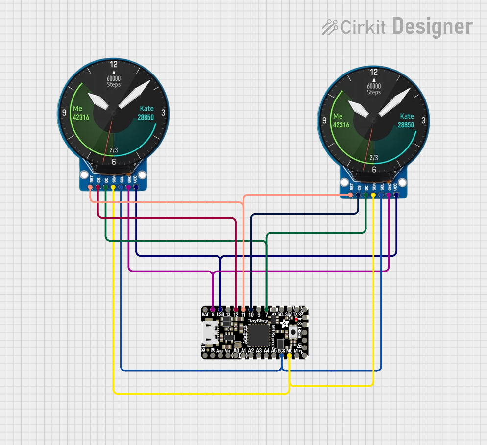

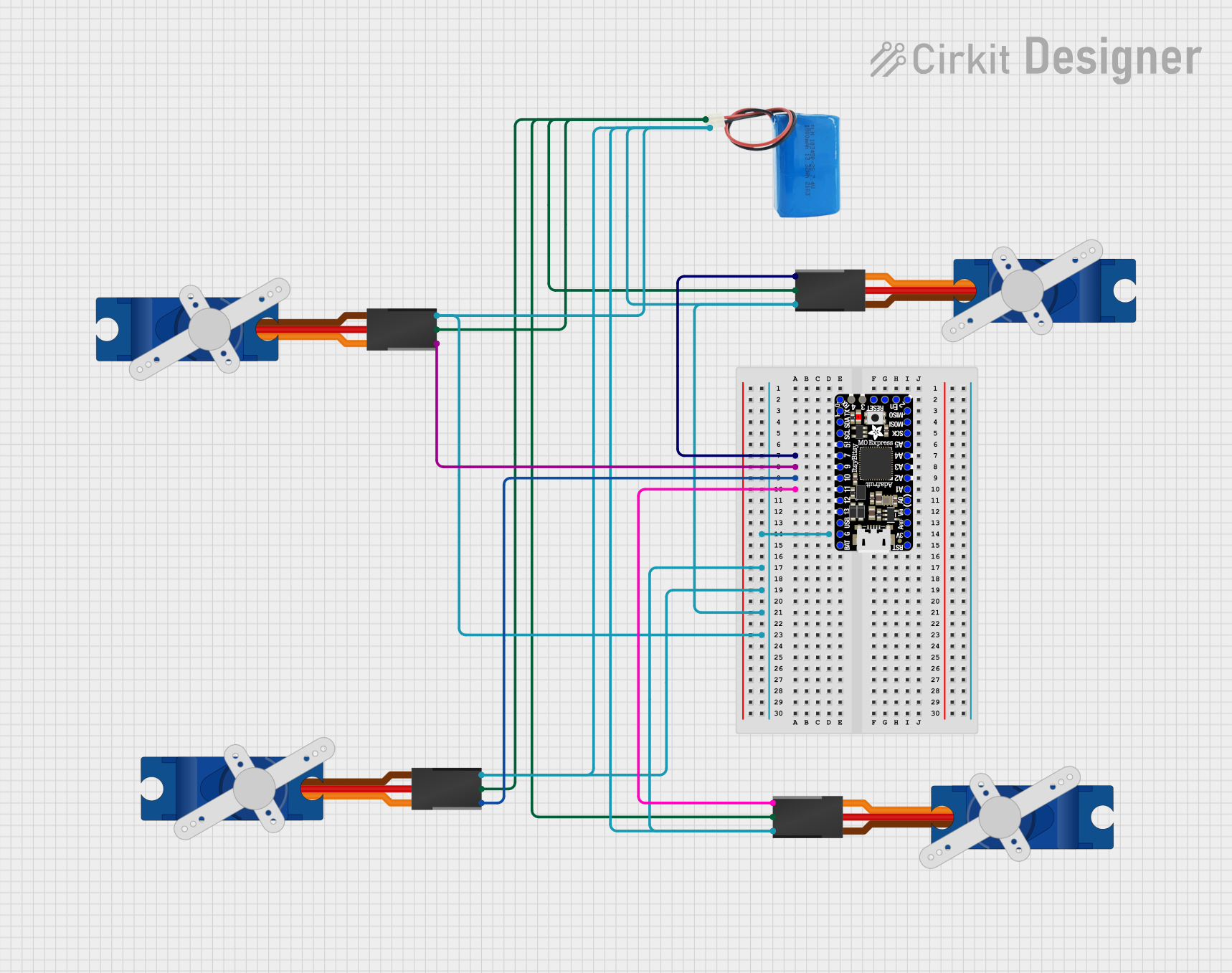

Explore Projects Built with Adafruit ItsyBitsy M4
Technical Specifications
Key Technical Details
- Microcontroller: ATSAMD51 32-bit Cortex M4 core running at 120 MHz
- Flash Memory: 512 KB
- RAM: 192 KB
- Operating Voltage: 3.3V
- I/O Pin Voltage: 3.3V (Do not apply more than 3.3V to any I/O pin)
- Digital I/O Pins: 23 pins
- PWM Channels: 10
- Analog Inputs: 6 x 12-bit ADC channels
- Analog Outputs: 1 x 10-bit DAC
- Interfaces: I2C, SPI, UART
- Clock Speed: 120 MHz
- USB: Micro-USB for programming and power
- Dimensions: 36mm x 18mm x 4mm / 1.4" x 0.7" x 0.16"
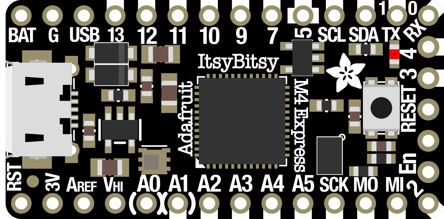
Pin Configuration and Descriptions
| Pin Number | Function | Description |
|---|---|---|
| 1 | A0/D0 | Analog input 0 or Digital I/O 0 |
| 2 | A1/D1 | Analog input 1 or Digital I/O 1 |
| 3 | A2/D2 | Analog input 2 or Digital I/O 2 |
| ... | ... | ... |
| 23 | A5/D21 | Analog input 5 or Digital I/O 21 |
| 24 | DAC0 | Digital-to-Analog Converter Output |
| 25 | SCK | SPI Clock |
| 26 | MISO | SPI Master In Slave Out |
| 27 | MOSI | SPI Master Out Slave In |
| 28 | SDA | I2C Data |
| 29 | SCL | I2C Clock |
| 30 | RX | UART Receive |
| 31 | TX | UART Transmit |
| USB | Micro-USB Port for programming and power supply |
(Note: This table is not exhaustive and serves as an example. Refer to the official pinout diagram for complete details.)
Usage Instructions
Integrating with a Circuit
To use the ItsyBitsy M4 in a circuit:
- Connect the board to your computer using a micro-USB cable.
- Ensure that the board is recognized by your computer and the appropriate drivers are installed.
- Use a breadboard and jumper wires to connect components to the ItsyBitsy M4's I/O pins.
- Pay attention to the operating voltage of 3.3V to avoid damaging the board.
Best Practices
- Always disconnect the ItsyBitsy M4 from power before making or altering connections.
- Use a voltage level shifter if you need to interface with 5V components.
- Avoid static discharge by grounding yourself before handling the board.
- Ensure that your power supply is stable and within the recommended voltage range.
Example Code for Arduino UNO
Here is a simple example of blinking an LED using the ItsyBitsy M4 with Arduino IDE:
// Define the LED pin
const int LED_PIN = 13;

void setup() {
  // Initialize the digital pin as an output.
  pinMode(LED_PIN, OUTPUT);
}

void loop() {
  // Turn the LED on (HIGH is the voltage level)
  digitalWrite(LED_PIN, HIGH);
  // Wait for a second
  delay(1000);
  // Turn the LED off by making the voltage LOW
  digitalWrite(LED_PIN, LOW);
  // Wait for a second
  delay(1000);
}
Remember to select the Adafruit ItsyBitsy M4 board from the Tools > Board menu in the Arduino IDE before uploading the code.
Troubleshooting and FAQs
Common Issues
- Board not recognized: Ensure that the micro-USB cable is properly connected and that the cable supports data transfer.
- Incorrect voltage: Verify that the power supply is 3.3V as higher voltages can damage the board.
- I/O pin not working: Check for any physical damage to the pin or solder joints and ensure that the pin is configured correctly in your code.
FAQs
Q: Can I power the ItsyBitsy M4 with a battery? A: Yes, you can power the board with a 3.7V LiPo battery connected to the VBAT pin.
Q: Is the ItsyBitsy M4 5V tolerant? A: No, the I/O pins are not 5V tolerant. Use a level shifter for interfacing with 5V logic.
Q: How do I reset the board? A: Briefly press the reset button on the board to reset it.
For more detailed troubleshooting, refer to the Adafruit support forums and the ItsyBitsy M4 product page.