How to Use KWH meter: Examples, Pinouts, and Specs
Introduction
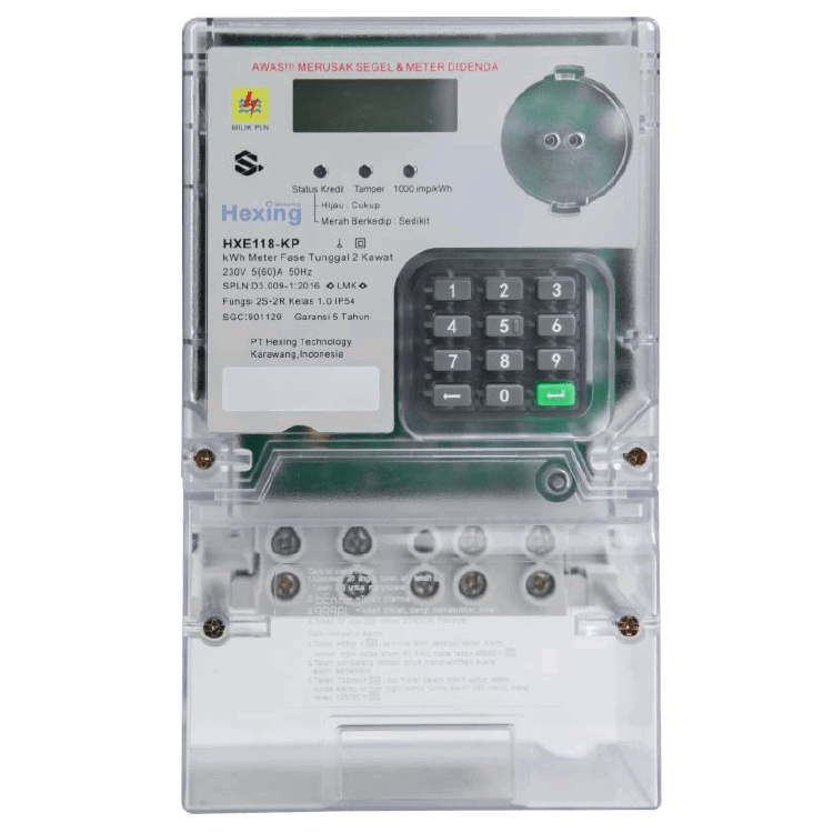
A KWH (Kilowatt-Hour) meter is an essential device used to measure the amount of electrical energy consumed by a residence, business, or an electrically powered device over time. The measurement is typically expressed in kilowatt-hours (kWh), which represents the energy usage equivalent to one kilowatt of power consumed over one hour.
Explore Projects Built with KWH meter

Explore Projects Built with KWH meter
Common Applications and Use Cases
- Monitoring energy consumption in residential, commercial, and industrial settings.
- Billing and energy usage tracking for utility companies.
- Energy management and optimization in smart homes.
- Integration with renewable energy systems to monitor production and consumption.
- Load analysis for electrical devices and appliances.
Technical Specifications
Below are the general technical specifications for a typical KWH meter. Note that specific models may vary slightly in their ratings and features.
Key Technical Details
- Input Voltage Range: 110V AC to 240V AC
- Frequency: 50Hz or 60Hz
- Current Rating: 5A to 100A (depending on the model)
- Accuracy Class: Class 1.0 or Class 2.0 (±1% or ±2% error)
- Display Type: LCD or mechanical dial
- Communication Interface (optional): RS485, Modbus, or wireless (e.g., Zigbee)
- Power Consumption: Typically less than 2W
- Operating Temperature: -20°C to 60°C
- Mounting Type: DIN rail or wall-mounted
Pin Configuration and Descriptions
The pin configuration for a KWH meter depends on whether it is single-phase or three-phase. Below is a typical pinout for a single-phase KWH meter:
| Pin Number | Label | Description |
|---|---|---|
| 1 | L (Line) | Live input from the power source. |
| 2 | N (Neutral) | Neutral input from the power source. |
| 3 | L (Load) | Live output to the load (appliances). |
| 4 | N (Load) | Neutral output to the load (appliances). |
For a three-phase KWH meter, the pinout may look like this:
| Pin Number | Label | Description |
|---|---|---|
| 1 | L1 | Phase 1 input from the power source. |
| 2 | L2 | Phase 2 input from the power source. |
| 3 | L3 | Phase 3 input from the power source. |
| 4 | N | Neutral input from the power source. |
| 5 | L1 (Load) | Phase 1 output to the load. |
| 6 | L2 (Load) | Phase 2 output to the load. |
| 7 | L3 (Load) | Phase 3 output to the load. |
| 8 | N (Load) | Neutral output to the load. |
Usage Instructions
How to Use the Component in a Circuit
- Safety First: Ensure the power supply is turned off before wiring the KWH meter.
- Wiring:
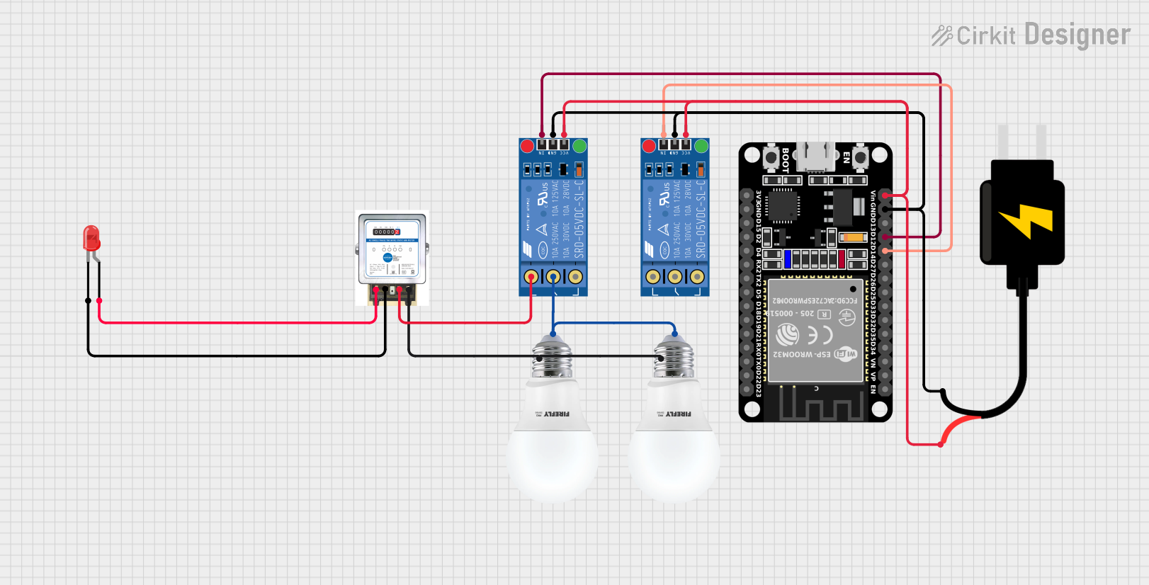
- For a single-phase meter, connect the live (L) and neutral (N) wires from the power source to the input terminals (Pins 1 and 2). Then, connect the live and neutral wires to the load (Pins 3 and 4).
- For a three-phase meter, connect the three phases (L1, L2, L3) and neutral (N) from the power source to the input terminals (Pins 1-4). Similarly, connect the output terminals (Pins 5-8) to the load.
- Mounting: Secure the meter on a DIN rail or wall mount as per the manufacturer's instructions.
- Power On: Turn on the power supply and verify that the meter display is functioning correctly.
- Reading the Meter: Observe the energy consumption on the display, typically shown in kWh.
Important Considerations and Best Practices
- Ensure the meter's current and voltage ratings match the system's requirements.
- Avoid overloading the meter beyond its rated capacity to prevent damage.
- For accurate readings, ensure all connections are secure and free from corrosion.
- If using a meter with communication capabilities (e.g., RS485), configure the communication settings as per the manufacturer's guidelines.
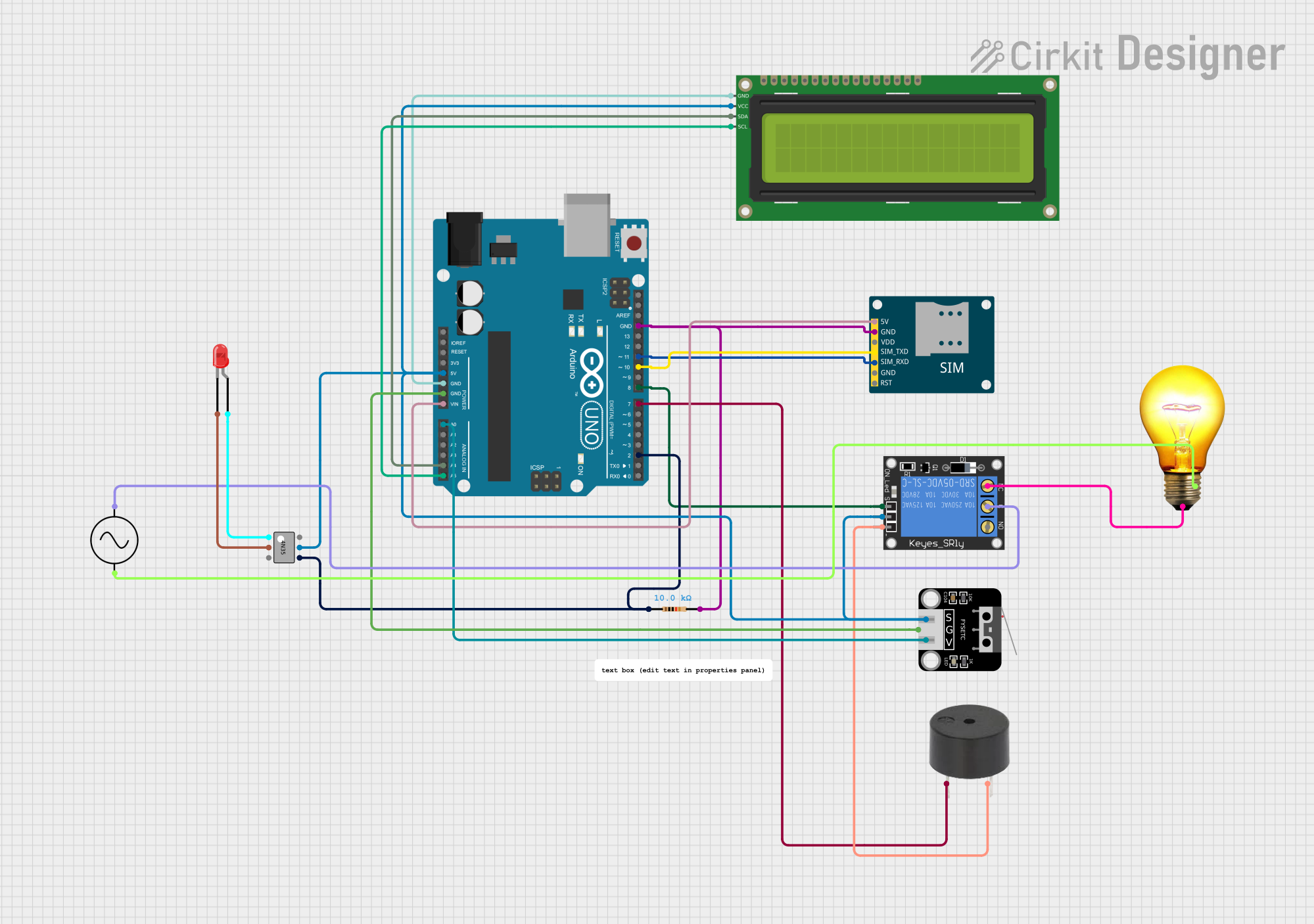
Example: Connecting a KWH Meter to an Arduino UNO
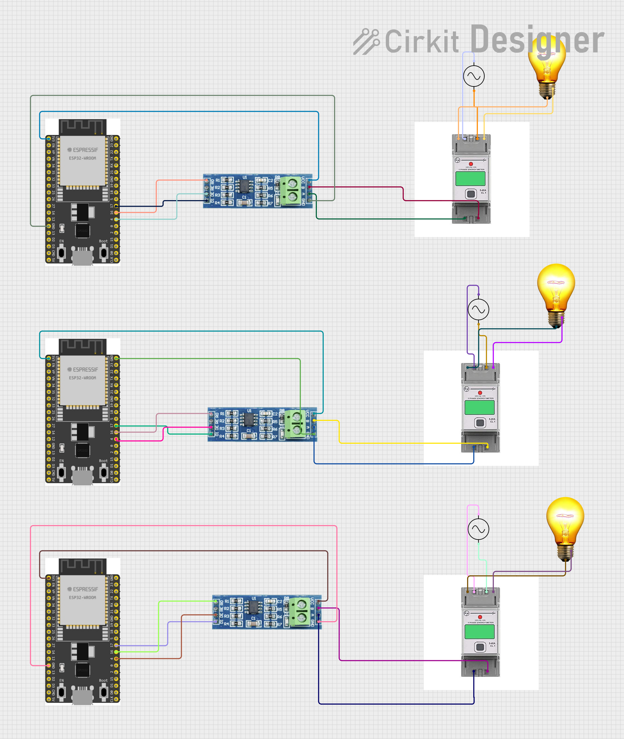
If the KWH meter supports communication via RS485, you can interface it with an Arduino UNO to read energy data. Below is an example code snippet:
#include <ModbusMaster.h> // Include the Modbus library

ModbusMaster node; // Create a ModbusMaster object

void setup() {
  Serial.begin(9600); // Initialize serial communication
  node.begin(1, Serial); // Set Modbus slave ID to 1 and use Serial for communication
}

void loop() {
  uint8_t result;
  uint16_t data[2];

  // Read energy consumption (e.g., register 0x0000 for kWh)
  result = node.readInputRegisters(0x0000, 2);

  if (result == node.ku8MBSuccess) {
    // Combine two 16-bit registers into a 32-bit value
    uint32_t energy = (node.getResponseBuffer(0) << 16) | node.getResponseBuffer(1);
    Serial.print("Energy Consumption (kWh): ");
    Serial.println(energy / 100.0); // Assuming the value is scaled by 100
  } else {
    Serial.println("Failed to read from KWH meter");
  }

  delay(1000); // Wait 1 second before the next read
}
Note: Ensure you use an RS485-to-TTL converter module to connect the KWH meter to the Arduino UNO.
Troubleshooting and FAQs
Common Issues Users Might Face
No Display or Power:
- Cause: Incorrect wiring or no power supply.
- Solution: Double-check the wiring and ensure the power source is active.
Inaccurate Readings:
- Cause: Loose connections or exceeding the meter's rated capacity.
- Solution: Tighten all connections and ensure the load is within the meter's specifications.
Communication Failure (RS485):
- Cause: Incorrect baud rate or wiring issues.
- Solution: Verify the baud rate and communication settings. Check the RS485 connections.
Meter Not Responding to Commands:
- Cause: Incorrect Modbus slave ID or register address.
- Solution: Confirm the correct slave ID and register address from the meter's datasheet.
Solutions and Tips for Troubleshooting
- Always refer to the manufacturer's manual for specific troubleshooting steps.
- Use a multimeter to verify voltage and current levels at the input and output terminals.
- For communication issues, use a protocol analyzer to debug RS485 signals.
By following this documentation, you can effectively use and troubleshoot a KWH meter in various applications.