Cirkit Designer
Your all-in-one circuit design IDE
Home /
Component Documentation
How to Use MB102 Breadboard Power Supply Module 3.3V/5V: Examples, Pinouts, and Specs
Introduction
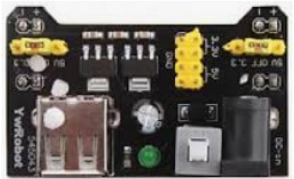
The MB102 Breadboard Power Supply Module is a versatile and compact power solution designed for electronic hobbyists and professionals alike. This module is commonly used to provide both 3.3V and 5V DC power to breadboard-based prototype circuits, making it an essential tool for developing microcontroller projects, testing circuits, and educational purposes.
Explore Projects Built with MB102 Breadboard Power Supply Module 3.3V/5V
Arduino UNO RFID Access Control System with LCD Feedback and Servo Operation
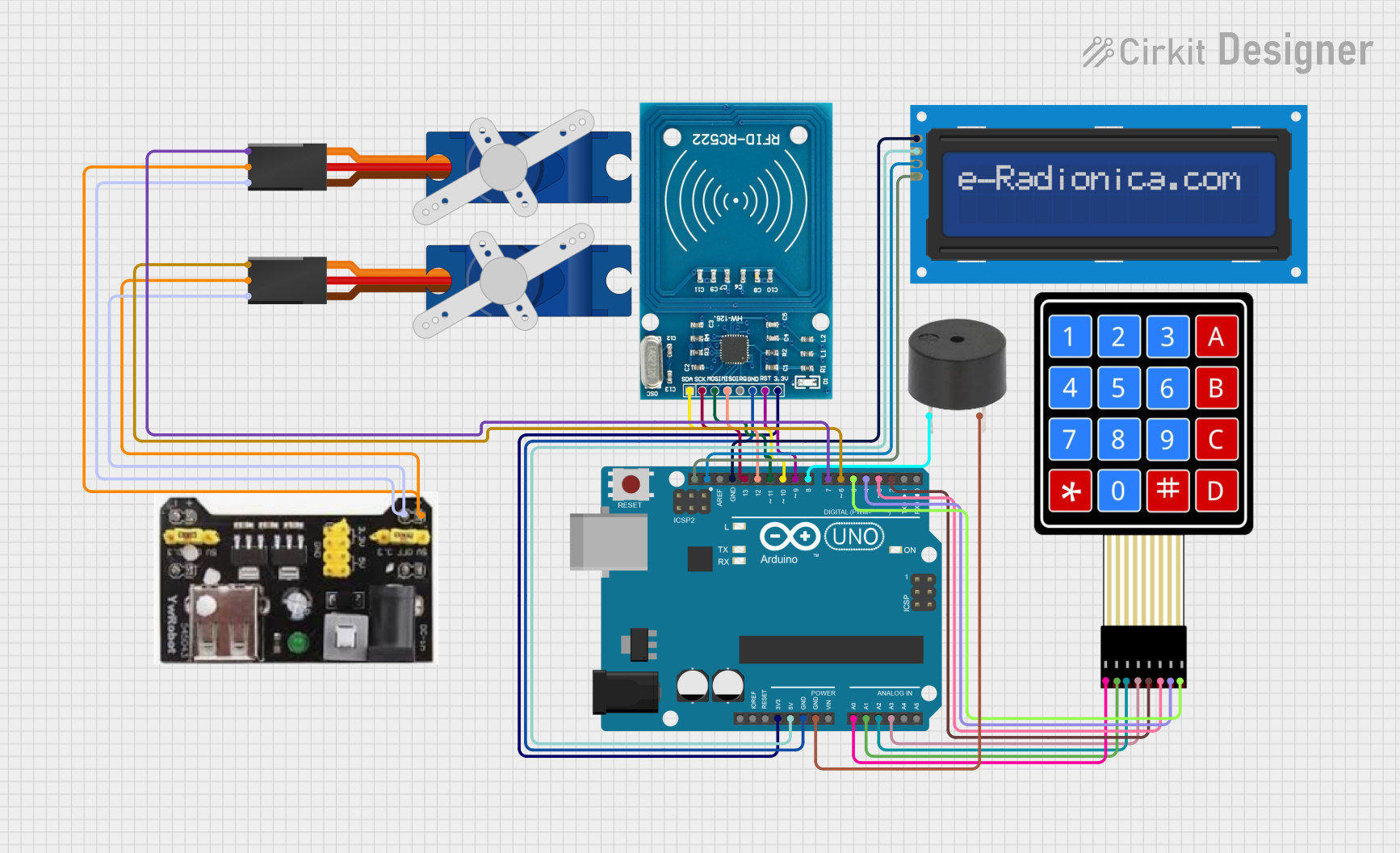
This circuit features an Arduino UNO as the central microcontroller, interfaced with an RFID-RC522 module for RFID reading capabilities, and a 16x2 LCD screen with I2C for display. It also includes a 4x4 membrane matrix keypad for user input, a buzzer for audio feedback, and two Tower Pro SG90 servos for actuation. The MB102 Breadboard Power Supply Module provides power to the servos, while the Arduino powers the other components.
Battery-Powered 18650 Li-ion Charger with USB Output and Adjustable Voltage Regulator

This circuit is a battery management and power supply system that uses three 3.7V batteries connected to a 3S 10A Li-ion 18650 Charger Protection Board Module for balanced charging and protection. The system includes a TP4056 Battery Charging Protection Module for additional charging safety, a Step Up Boost Power Converter to regulate and boost the voltage, and a USB regulator to provide a stable 5V output, controlled by a push switch.
Battery-Powered Arduino UNO and ESP-8266 Smart Controller with LCD and RTC

This circuit is a power management and control system that uses a 12V power supply and a 18650 Li-ion battery pack to provide a stable 5V output through a step-down buck converter. It includes an Arduino UNO, an ESP-8266 controller, a DS1307 RTC module, and a 20x4 I2C LCD display for monitoring and control purposes. The ULN2003A breakout board is used for driving higher current loads.
ESP8266 NodeMCU with LoRa and RS-485 Communication and Ethernet Connectivity

This circuit serves as a multi-protocol communication hub featuring two ESP8266 NodeMCUs for processing, each connected to a LoRa Ra-02 SX1278 for long-range wireless communication. One NodeMCU is also connected to an RS-485 module for serial communication and a W5500 Ethernet module for network connectivity, with MB102 modules supplying power.
Explore Projects Built with MB102 Breadboard Power Supply Module 3.3V/5V
Arduino UNO RFID Access Control System with LCD Feedback and Servo Operation
This circuit features an Arduino UNO as the central microcontroller, interfaced with an RFID-RC522 module for RFID reading capabilities, and a 16x2 LCD screen with I2C for display. It also includes a 4x4 membrane matrix keypad for user input, a buzzer for audio feedback, and two Tower Pro SG90 servos for actuation. The MB102 Breadboard Power Supply Module provides power to the servos, while the Arduino powers the other components.
Battery-Powered 18650 Li-ion Charger with USB Output and Adjustable Voltage Regulator
This circuit is a battery management and power supply system that uses three 3.7V batteries connected to a 3S 10A Li-ion 18650 Charger Protection Board Module for balanced charging and protection. The system includes a TP4056 Battery Charging Protection Module for additional charging safety, a Step Up Boost Power Converter to regulate and boost the voltage, and a USB regulator to provide a stable 5V output, controlled by a push switch.
Battery-Powered Arduino UNO and ESP-8266 Smart Controller with LCD and RTC
This circuit is a power management and control system that uses a 12V power supply and a 18650 Li-ion battery pack to provide a stable 5V output through a step-down buck converter. It includes an Arduino UNO, an ESP-8266 controller, a DS1307 RTC module, and a 20x4 I2C LCD display for monitoring and control purposes. The ULN2003A breakout board is used for driving higher current loads.
ESP8266 NodeMCU with LoRa and RS-485 Communication and Ethernet Connectivity
This circuit serves as a multi-protocol communication hub featuring two ESP8266 NodeMCUs for processing, each connected to a LoRa Ra-02 SX1278 for long-range wireless communication. One NodeMCU is also connected to an RS-485 module for serial communication and a W5500 Ethernet module for network connectivity, with MB102 modules supplying power.
Common Applications and Use Cases
- Powering microcontroller platforms such as Arduino, Raspberry Pi, and PIC.
- Providing power to sensor modules, displays, and other electronic components during prototyping.
- Use in educational settings for teaching electronics and circuit design.
Technical Specifications
Key Technical Details
- Input Voltage: 6.5V to 12V DC via barrel jack or USB power.
- Output Voltage: 3.3V and 5V DC selectable via jumpers.
- Maximum Output Current:
- 700 mA when powered via USB.
- Up to 1A when powered via DC barrel jack (depending on input voltage and thermal conditions).
- Onboard Voltage Regulator for stable output.
- Power Rails: Dual rail design, providing both voltages simultaneously.
Pin Configuration and Descriptions
| Pin Number | Description | Voltage Level |
|---|---|---|
| 1 | Ground (GND) | 0V |
| 2 | Output Voltage Select (VOUT) | 3.3V or 5V |
| 3 | Input Voltage (VIN) | 6.5V to 12V |
Usage Instructions
How to Use the Component in a Circuit
- Connect the MB102 module to the breadboard aligning the pins with the power rails.
- Select the desired output voltage (3.3V or 5V) by placing the jumper on the appropriate header.
- Provide input power through the USB connector or the DC barrel jack.
- Connect the power and ground lines from the module to your circuit.
Important Considerations and Best Practices
- Ensure the input voltage is within the specified range to prevent damage.
- Do not exceed the maximum output current to avoid overheating and potential failure.
- Always disconnect power before making or altering connections to prevent shorts.
- Use decoupling capacitors close to power pins of sensitive components to reduce noise.
Troubleshooting and FAQs
Common Issues Users Might Face
- No Output Voltage: Check input power source and connections. Ensure the jumper is correctly placed for the desired voltage.
- Voltage Fluctuations: Ensure the input voltage is stable and within the specified range. Check for overloading beyond the current limit.
- Overheating: Reduce the load if the module becomes too hot. Ensure adequate ventilation around the module.
Solutions and Tips for Troubleshooting
- Verify connections and input power with a multimeter.
- If the module fails to power up, inspect for any visible damage or loose components.
- For noise-sensitive applications, add additional filtering on the output lines.
Example Code for Arduino UNO
// Example code to demonstrate the use of the MB102 with an Arduino UNO

void setup() {
  // Set up the built-in LED pin as an output for testing
  pinMode(LED_BUILTIN, OUTPUT);
}

void loop() {
  // Turn the LED on for one second
  digitalWrite(LED_BUILTIN, HIGH);
  delay(1000);
  // Turn the LED off for one second
  digitalWrite(LED_BUILTIN, LOW);
  delay(1000);
  // This will create a blinking effect using the power from the MB102 module
}
Note: The above code assumes that the MB102 module is correctly set up and providing power to the Arduino UNO. Ensure that the voltage selection jumper on the MB102 is set to 5V when powering the Arduino UNO.
Remember to always double-check your connections and adhere to the best practices mentioned in the usage instructions to ensure a safe and successful project.