How to Use HMI DGUS: Examples, Pinouts, and Specs
Introduction
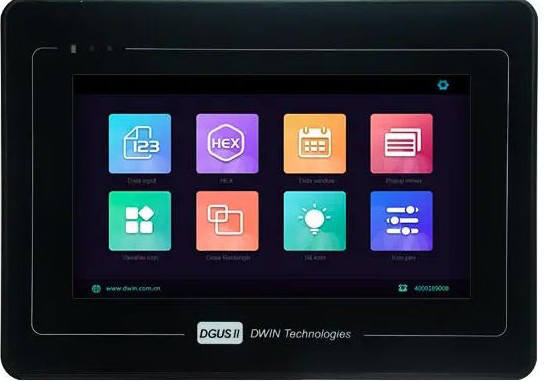
The HMI DGUS (Human-Machine Interface) is a versatile graphical interface designed for controlling and monitoring industrial processes. Manufactured by HMI DGUS, this component provides a user-friendly platform for interacting with machines via touch screens or physical buttons. It is capable of displaying real-time data, receiving user input, and enabling system adjustments, making it an essential tool in automation and industrial control systems.
Explore Projects Built with HMI DGUS
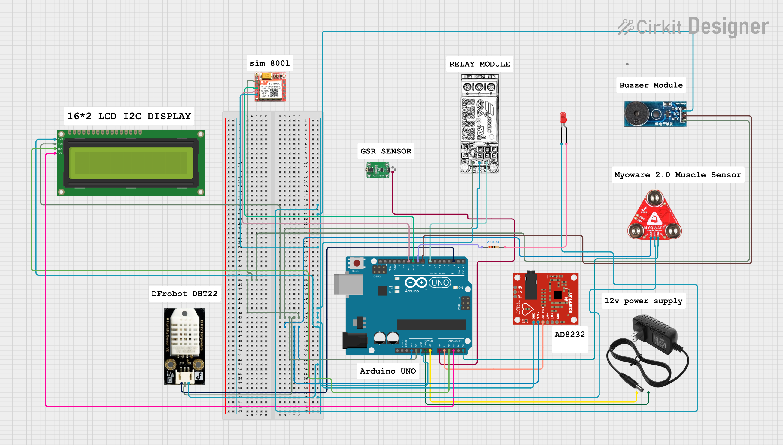
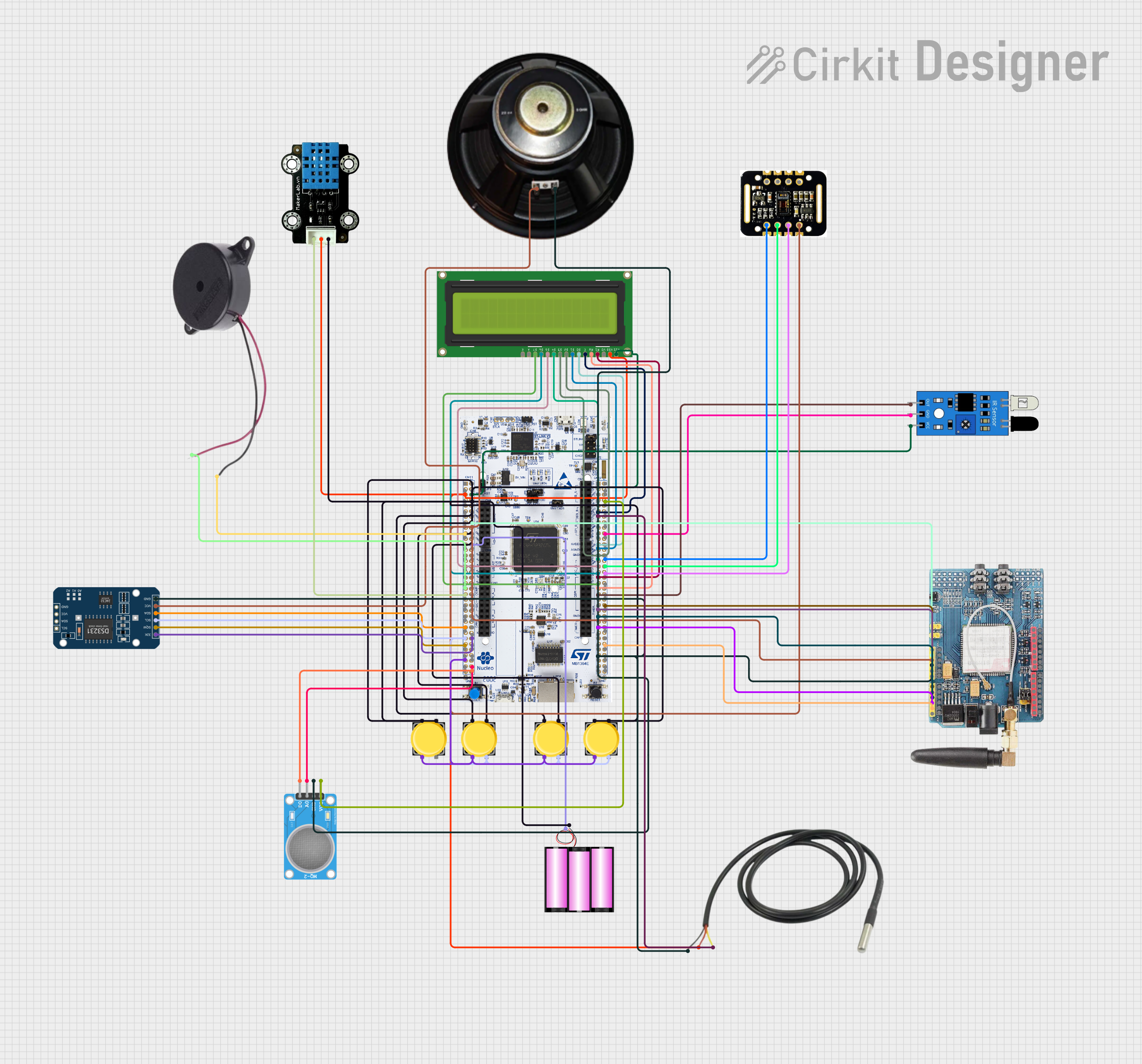
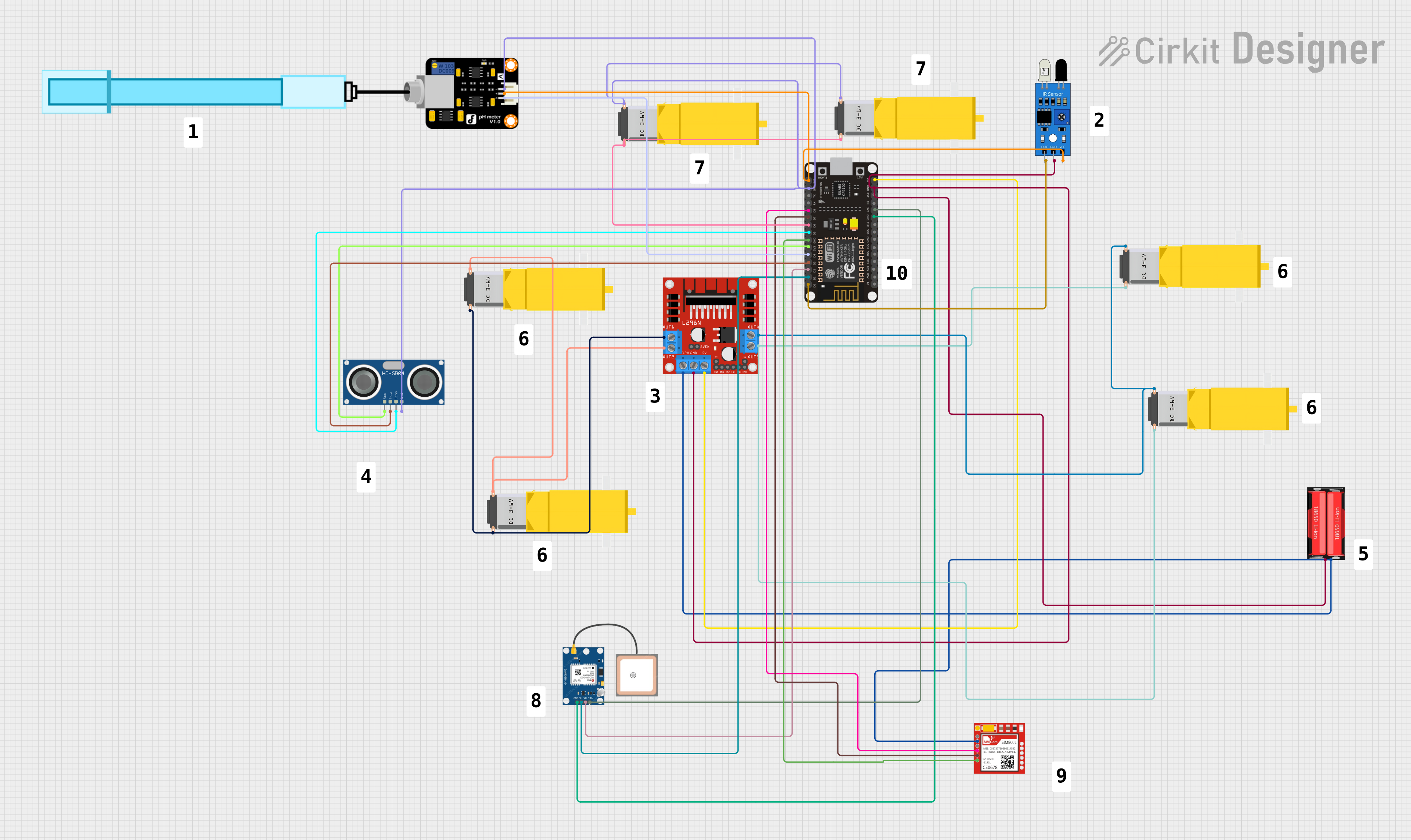
Explore Projects Built with HMI DGUS
Common Applications and Use Cases
- Industrial automation and process control
- Home automation systems
- Medical equipment interfaces
- Smart appliances
- Monitoring and control of IoT devices
- Automotive dashboards and control panels
Technical Specifications
Key Technical Details
| Parameter | Specification |
|---|---|
| Manufacturer | HMI DGUS |
| Part ID | HMI DGUS |
| Display Type | TFT LCD with touch screen |
| Screen Sizes Available | 3.5", 4.3", 5", 7", 10.1" |
| Resolution | Up to 1024x600 pixels |
| Input Voltage | 5V DC or 12V DC (model-dependent) |
| Communication Protocols | UART, RS232, RS485, CAN |
| Flash Memory | Up to 128MB |
| Operating Temperature | -20°C to 70°C |
| Touch Panel Type | Resistive or Capacitive (model-dependent) |
| Backlight | LED |
| Power Consumption | Typically < 5W |
Pin Configuration and Descriptions
The pin configuration may vary depending on the specific model of the HMI DGUS. Below is a general pinout for a typical HMI DGUS module:
| Pin Number | Pin Name | Description |
|---|---|---|
| 1 | VCC | Power supply input (5V or 12V, model-dependent) |
| 2 | GND | Ground connection |
| 3 | TX | UART Transmit (data output) |
| 4 | RX | UART Receive (data input) |
| 5 | CAN_H | CAN Bus High |
| 6 | CAN_L | CAN Bus Low |
| 7 | RS485_A | RS485 Data Line A |
| 8 | RS485_B | RS485 Data Line B |
Usage Instructions
How to Use the Component in a Circuit
- Power Supply: Connect the VCC pin to a regulated 5V or 12V DC power source (depending on the model) and the GND pin to the ground of your circuit.
- Communication Interface: Choose the appropriate communication protocol (UART, RS232, RS485, or CAN) based on your application. For example:
- For UART communication, connect the TX pin of the HMI DGUS to the RX pin of your microcontroller and the RX pin of the HMI DGUS to the TX pin of your microcontroller.
- For RS485, connect RS485_A and RS485_B to the corresponding lines of your RS485 network.
- Touch Screen Setup: Configure the touch screen interface using the DGUS software provided by the manufacturer. This software allows you to design graphical user interfaces (GUIs) and upload them to the HMI DGUS module.
- Data Exchange: Use the selected communication protocol to send and receive data between the HMI DGUS and your microcontroller or PLC.
Important Considerations and Best Practices
- Power Supply: Ensure the power supply voltage matches the requirements of your specific HMI DGUS model to avoid damage.
- Communication Settings: Configure the baud rate, parity, and other communication parameters correctly to ensure reliable data exchange.
- Software Configuration: Use the DGUS software to design and upload your GUI. Follow the manufacturer's guidelines for optimal performance.
- EMI Protection: In industrial environments, use proper shielding and grounding to minimize electromagnetic interference (EMI).
- Firmware Updates: Regularly check for firmware updates from the manufacturer to ensure compatibility and access to new features.
Example: Connecting HMI DGUS to Arduino UNO
Below is an example of how to connect and communicate with the HMI DGUS using an Arduino UNO via UART:
Circuit Connections
- Connect the VCC pin of the HMI DGUS to the 5V pin of the Arduino UNO.
- Connect the GND pin of the HMI DGUS to the GND pin of the Arduino UNO.
- Connect the TX pin of the HMI DGUS to the RX pin of the Arduino UNO.
- Connect the RX pin of the HMI DGUS to the TX pin of the Arduino UNO.
Arduino Code
// Include the SoftwareSerial library for UART communication
#include <SoftwareSerial.h>

// Define RX and TX pins for SoftwareSerial
SoftwareSerial HMI(10, 11); // RX = pin 10, TX = pin 11

void setup() {
  // Initialize serial communication with the HMI DGUS
  HMI.begin(9600); // Set baud rate to 9600 (adjust as needed)
  Serial.begin(9600); // For debugging via Serial Monitor

  // Send an initialization message to the HMI DGUS
  HMI.println("HMI DGUS Initialized");
  Serial.println("HMI DGUS Communication Started");
}

void loop() {
  // Check if data is available from the HMI DGUS
  if (HMI.available()) {
    String data = HMI.readString(); // Read data from HMI DGUS
    Serial.println("Received from HMI: " + data); // Print to Serial Monitor
  }

  // Send a test message to the HMI DGUS
  HMI.println("Hello, HMI!");
  delay(1000); // Wait for 1 second
}
Troubleshooting and FAQs
Common Issues and Solutions
No Display or Backlight:
- Cause: Incorrect power supply voltage or loose connections.
- Solution: Verify the power supply voltage and ensure all connections are secure.
Communication Failure:
- Cause: Incorrect baud rate or communication settings.
- Solution: Check and match the communication settings (baud rate, parity, etc.) between the HMI DGUS and the microcontroller/PLC.
Touch Screen Not Responding:
- Cause: Calibration issue or damaged touch panel.
- Solution: Recalibrate the touch screen using the DGUS software or consult the manufacturer for repair.
Data Corruption:
- Cause: Electromagnetic interference (EMI) or incorrect wiring.
- Solution: Use shielded cables and ensure proper grounding.
FAQs
Q1: Can I use the HMI DGUS with a Raspberry Pi?
A1: Yes, the HMI DGUS can be connected to a Raspberry Pi using UART, RS232, or other supported communication protocols. Ensure the voltage levels are compatible or use a level shifter if needed.
Q2: How do I update the firmware on the HMI DGUS?
A2: Firmware updates can be performed using the manufacturer's software and a USB-to-serial adapter. Follow the instructions provided in the user manual.
Q3: What software is required to design GUIs for the HMI DGUS?
A3: The DGUS software provided by the manufacturer is used to design and upload GUIs. It is typically available for download on the manufacturer's website.
Q4: Can I use the HMI DGUS in outdoor environments?
A4: Some models are designed for outdoor use and feature higher operating temperature ranges and sunlight-readable displays. Check the specifications of your specific model.