How to Use BD140: Examples, Pinouts, and Specs
Introduction
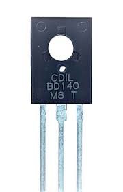
The BD140 is a PNP bipolar junction transistor (BJT) manufactured by STMicroelectronics. It is widely used in amplification and switching applications due to its robust design and reliable performance. With a maximum collector current of 1.5A and a maximum collector-emitter voltage of 60V, the BD140 is suitable for medium-power electronic circuits. Its versatility makes it a popular choice in audio amplifiers, motor drivers, and general-purpose switching circuits.
Explore Projects Built with BD140
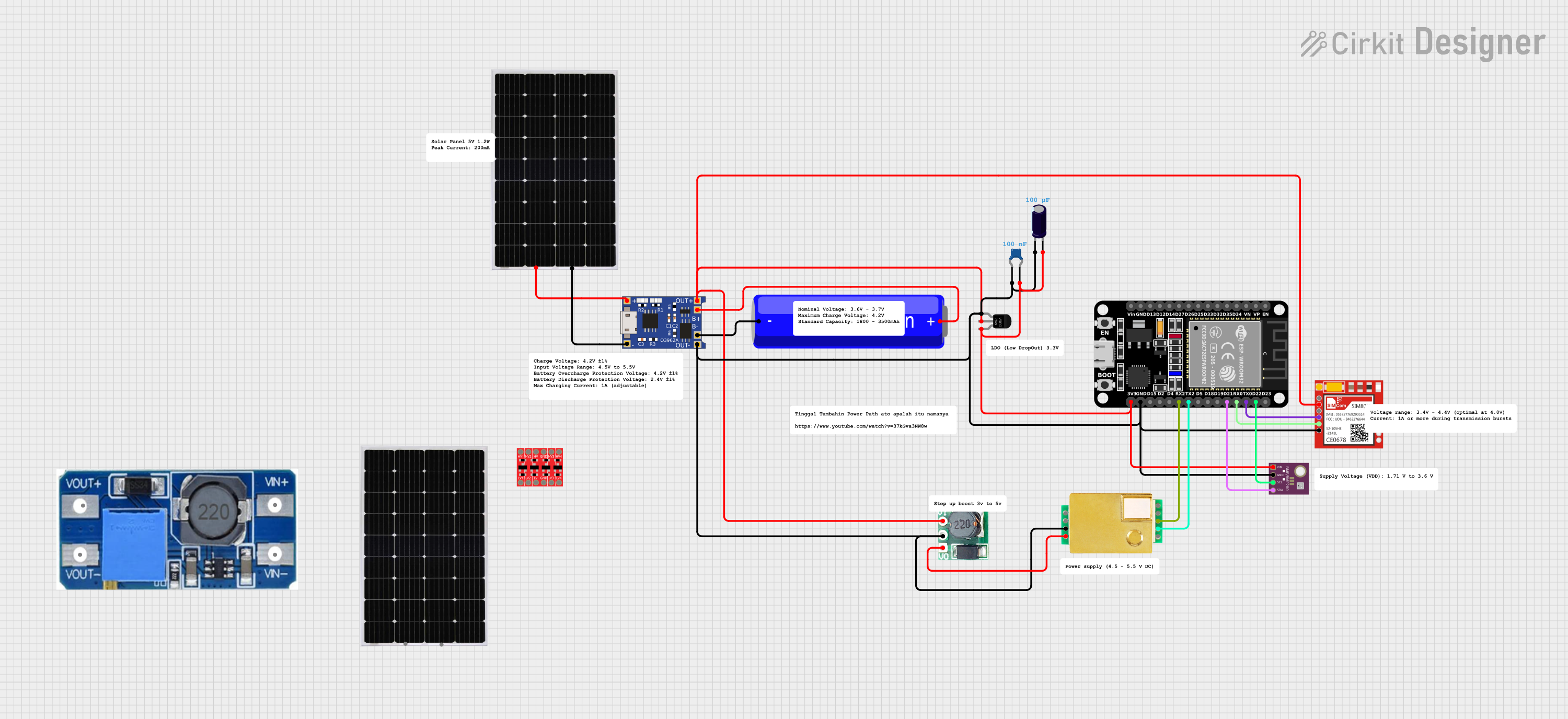
Explore Projects Built with BD140
Common Applications
- Audio amplification circuits
- Motor control and driver circuits
- Signal switching in electronic devices
- Voltage regulation and power management
- General-purpose medium-power applications
Technical Specifications
Key Specifications
| Parameter | Value |
|---|---|
| Manufacturer | STMicroelectronics |
| Part Number | BD140 |
| Transistor Type | PNP |
| Maximum Collector-Emitter Voltage (VCEO) | 60V |
| Maximum Collector Current (IC) | 1.5A |
| Maximum Power Dissipation (PD) | 12.5W (at Tcase = 25°C) |
| DC Current Gain (hFE) | 40 to 250 (depending on IC) |
| Transition Frequency (fT) | 190 MHz |
| Operating Temperature Range | -55°C to +150°C |
| Package Type | TO-126 |
Pin Configuration
The BD140 transistor comes in a TO-126 package with three pins. The pinout is as follows:
| Pin Number | Pin Name | Description |
|---|---|---|
| 1 | Base | Controls the transistor's operation |
| 2 | Collector | Current flows into this pin |
| 3 | Emitter | Current flows out of this pin |
The pin layout (viewed from the front of the flat side of the package) is shown below:
   _______
  |       |
  |       |
  |_______|
   | | |
   1 2 3
   B C E
Usage Instructions
Using the BD140 in a Circuit
The BD140 is typically used in circuits where a PNP transistor is required for amplification or switching. Below are the steps to use the BD140 in a basic circuit:
Determine the Operating Region: Ensure the transistor operates in the desired region (cutoff, active, or saturation) by applying the appropriate base-emitter voltage (VBE).
- For switching applications, drive the base with sufficient current to fully saturate the transistor.
- For amplification, bias the transistor in the active region.
Base Resistor Selection: Use a resistor to limit the base current (IB). The value of the resistor can be calculated using Ohm's law: [ R_B = \frac{V_{in} - V_{BE}}{I_B} ] where Vin is the input voltage, VBE is typically 0.7V, and IB is the required base current.
Connect the Load: Place the load (e.g., motor, LED, or speaker) between the collector and the positive supply voltage (VCC).
Power Dissipation: Ensure the power dissipation (PD) does not exceed the maximum rating of 12.5W. Use a heatsink if necessary.
Example: Controlling an LED with Arduino UNO
The BD140 can be used to control high-current devices like LEDs with an Arduino UNO. Below is an example circuit and code:
Circuit Description
- The BD140's emitter is connected to the positive supply (VCC).
- The collector is connected to the LED and a current-limiting resistor.
- The base is connected to an Arduino digital pin through a base resistor.
Arduino Code
// Define the pin connected to the BD140 base
const int transistorBasePin = 9;

void setup() {
  // Set the transistor base pin as an output
  pinMode(transistorBasePin, OUTPUT);
}

void loop() {
  // Turn the LED on by driving the transistor base high
  digitalWrite(transistorBasePin, HIGH);
  delay(1000); // Keep the LED on for 1 second

  // Turn the LED off by driving the transistor base low
  digitalWrite(transistorBasePin, LOW);
  delay(1000); // Keep the LED off for 1 second
}
Important Considerations
- Base Current: Ensure the base current (IB) is sufficient to drive the desired collector current (IC). Use the formula: [ I_B = \frac{I_C}{h_{FE}} ] where hFE is the DC current gain.
- Heatsinking: For high-power applications, attach a heatsink to the BD140 to prevent overheating.
- Polarity: Double-check the polarity of the connections, as reversing the collector and emitter can damage the transistor.
Troubleshooting and FAQs
Common Issues
Transistor Not Switching Properly
- Cause: Insufficient base current.
- Solution: Check the base resistor value and ensure the base current is adequate.
Overheating
- Cause: Excessive power dissipation.
- Solution: Use a heatsink or reduce the load current.
No Output Signal
- Cause: Incorrect pin connections or damaged transistor.
- Solution: Verify the pin connections and replace the transistor if necessary.
Low Amplification
- Cause: Incorrect biasing or low hFE.
- Solution: Adjust the biasing circuit and ensure the transistor is operating in the active region.
FAQs
Q1: Can the BD140 be used for high-frequency applications?
A1: Yes, the BD140 has a transition frequency (fT) of 190 MHz, making it suitable for some high-frequency applications.
Q2: What is the maximum voltage the BD140 can handle?
A2: The BD140 can handle a maximum collector-emitter voltage (VCEO) of 60V.
Q3: Can the BD140 be used with an NPN transistor?
A3: Yes, the BD140 can be paired with an NPN transistor (e.g., BD139) in push-pull amplifier or complementary circuits.
Q4: How do I protect the BD140 from damage?
A4: Use a base resistor to limit the base current, and ensure the load does not exceed the maximum collector current (1.5A). Additionally, use a heatsink for high-power applications.