
How to Use IR Receiver Mudule: Examples, Pinouts, and Specs
 Design with IR Receiver Mudule in Cirkit Designer
Introduction
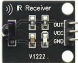
The IR Receiver Module (part ID: v1222) is a compact and efficient device designed to detect and process infrared (IR) signals emitted by remote controls and other IR sources. It converts the received IR light into an electrical signal, making it suitable for integration with microcontrollers, such as Arduino, and other electronic systems. This module is widely used in applications like remote-controlled devices, home automation systems, and IR-based communication.
Explore Projects Built with IR Receiver Mudule
 Open Project in Cirkit Designer
 Open Project in Cirkit Designer
 Open Project in Cirkit Designer
 Open Project in Cirkit Designer
Explore Projects Built with IR Receiver Mudule
Open Project in Cirkit DesignerOpen Project in Cirkit DesignerOpen Project in Cirkit DesignerOpen Project in Cirkit DesignerCommon Applications
- Remote control signal decoding
- Home automation and smart appliances
- IR-based wireless communication
- Consumer electronics (e.g., TVs, DVD players)
- Robotics and hobbyist projects
Technical Specifications
The following table outlines the key technical details of the IR Receiver Module (v1222):
| Parameter | Value |
|---|---|
| Operating Voltage | 2.7V to 5.5V |
| Operating Current | ≤ 1.5 mA |
| Carrier Frequency | 38 kHz (typical) |
| Reception Distance | Up to 10 meters (line of sight) |
| Reception Angle | ±45° |
| Output Signal | Digital (active low) |
| Response Time | ≤ 400 µs |
| Operating Temperature | -25°C to +85°C |
| Dimensions | 7.8mm x 5.8mm x 3.1mm |
Pin Configuration and Descriptions
The IR Receiver Module typically has three pins, as described in the table below:
| Pin | Name | Description |
|---|---|---|
| 1 | VCC | Power supply pin. Connect to a voltage source between 2.7V and 5.5V. |
| 2 | GND | Ground pin. Connect to the ground of the circuit. |
| 3 | OUT | Digital output pin. Outputs a low signal when an IR signal is detected. |
Usage Instructions
How to Use the IR Receiver Module in a Circuit
- Power the Module: Connect the
VCCpin to a 3.3V or 5V power source and theGNDpin to the ground of your circuit. - Connect the Output: Connect the
OUTpin to a digital input pin of your microcontroller or other logic-level device. - Add a Pull-Up Resistor: If necessary, use a pull-up resistor (e.g., 10kΩ) on the
OUTpin to ensure a stable high signal when no IR signal is detected. - Position the Module: Ensure the IR receiver is positioned to face the IR source for optimal signal reception.
- Decode the Signal: Use a microcontroller or IR decoding library to process the digital output and interpret the received IR signal.
Important Considerations and Best Practices
- Avoid Ambient IR Interference: Ensure the module is not exposed to direct sunlight or other strong IR sources, as this can interfere with signal reception.
- Use a Compatible Carrier Frequency: The module is optimized for a 38 kHz carrier frequency. Ensure your IR source matches this frequency.
- Maintain Line of Sight: For best performance, ensure there is a clear line of sight between the IR source and the receiver.
- Decoupling Capacitor: Place a small decoupling capacitor (e.g., 0.1 µF) between
VCCandGNDto reduce noise and improve stability.
Example: Using the IR Receiver Module with Arduino UNO
Below is an example of how to connect and use the IR Receiver Module (v1222) with an Arduino UNO to decode IR signals:
Circuit Connections
- Connect the
VCCpin of the IR receiver to the 5V pin of the Arduino. - Connect the
GNDpin of the IR receiver to the GND pin of the Arduino. - Connect the
OUTpin of the IR receiver to digital pin 2 of the Arduino.
Arduino Code
#include <IRremote.h> // Include the IRremote library for decoding IR signals

const int RECV_PIN = 2; // Define the pin connected to the IR receiver's OUT pin
IRrecv irrecv(RECV_PIN); // Create an IRrecv object
decode_results results;  // Create a decode_results object to store decoded data

void setup() {
  Serial.begin(9600); // Initialize serial communication for debugging
  irrecv.enableIRIn(); // Start the IR receiver
  Serial.println("IR Receiver Module is ready to receive signals.");
}

void loop() {
  if (irrecv.decode(&results)) { // Check if an IR signal is received
    Serial.print("IR Code Received: ");
    Serial.println(results.value, HEX); // Print the received IR code in hexadecimal
    irrecv.resume(); // Prepare to receive the next signal
  }
}
Notes:
- Install the
IRremotelibrary in the Arduino IDE before uploading the code. - The received IR code will be displayed in the Serial Monitor. Use this code to identify and respond to specific remote control buttons.
Troubleshooting and FAQs
Common Issues and Solutions
No Signal Detected
- Cause: Incorrect wiring or insufficient power supply.
- Solution: Double-check the connections and ensure the
VCCpin is receiving the correct voltage.
Unstable or Noisy Output
- Cause: Electrical noise or lack of a pull-up resistor.
- Solution: Add a pull-up resistor (e.g., 10kΩ) to the
OUTpin and use a decoupling capacitor betweenVCCandGND.
Short Reception Range
- Cause: Obstructions or weak IR source.
- Solution: Ensure a clear line of sight and verify the IR source's strength and carrier frequency.
Interference from Ambient Light
- Cause: Exposure to sunlight or other strong IR sources.
- Solution: Use the module in a controlled environment or shield it from ambient IR interference.
FAQs
Q1: Can this module work with a 3.3V microcontroller?
A1: Yes, the IR Receiver Module (v1222) operates within a voltage range of 2.7V to 5.5V, making it compatible with 3.3V systems.
Q2: What is the maximum distance for signal reception?
A2: The module can receive IR signals from up to 10 meters, provided there is a clear line of sight and the IR source is strong enough.
Q3: Can I use this module to control multiple devices?
A3: Yes, by decoding the IR signals, you can program your microcontroller to control multiple devices based on the received codes.
Q4: Does the module support protocols like NEC or Sony?
A4: The module itself does not decode protocols but outputs the raw signal. Use an IR decoding library (e.g., IRremote) to interpret specific protocols.
Q5: How do I know if the module is working?
A5: Use a serial monitor to check if the module outputs data when an IR signal is sent. Alternatively, use an LED to test the output pin's activity.