How to Use RoboRio 2.0: Examples, Pinouts, and Specs
Introduction
The RoboRio 2.0, manufactured by NI (National Instruments), is a compact and rugged embedded controller specifically designed for robotics applications. It features a powerful processor, multiple I/O ports, and support for various programming languages, making it an ideal choice for controlling robots in competitive environments such as the FIRST Robotics Competition (FRC). Its robust design ensures reliable performance in demanding conditions, while its versatility allows for seamless integration with a wide range of sensors, actuators, and communication devices.
Explore Projects Built with RoboRio 2.0
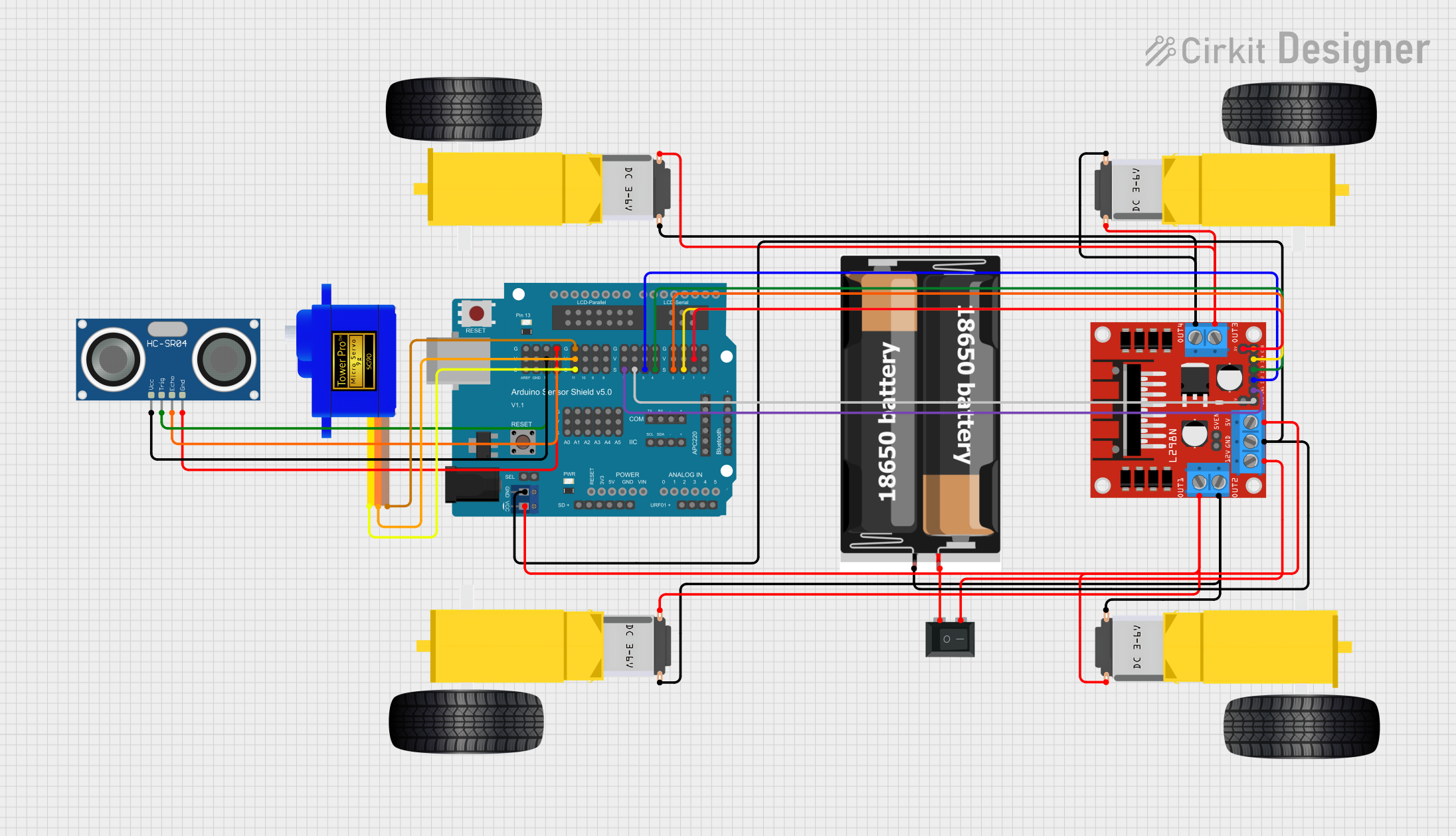
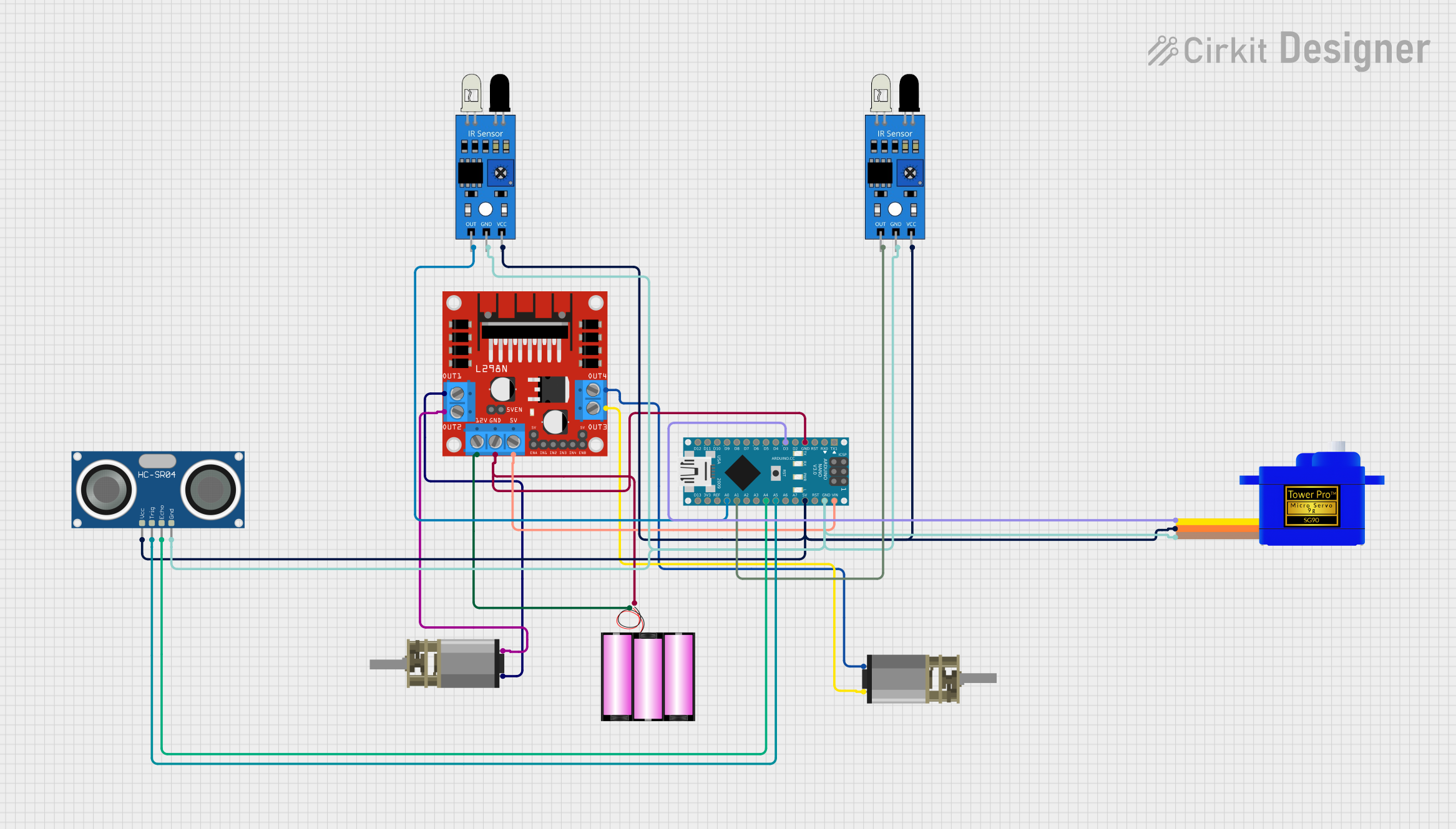
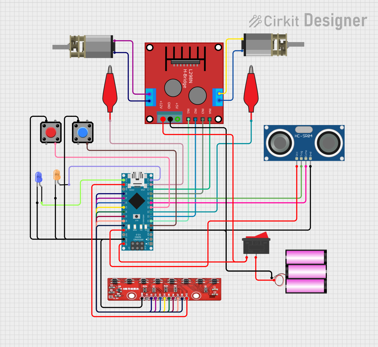

Explore Projects Built with RoboRio 2.0
Common Applications and Use Cases
- Robotics competitions (e.g., FIRST Robotics Competition)
- Autonomous robotic systems
- Industrial automation and control
- Educational robotics projects
- Prototyping and testing of robotic designs
Technical Specifications
Key Technical Details
| Specification | Value |
|---|---|
| Processor | Xilinx Zynq-7000 ARM Cortex-A9 Dual-Core |
| FPGA | Xilinx Artix-7 FPGA |
| Operating Voltage | 7V to 16V |
| Digital I/O Ports | 10 (5V-tolerant) |
| PWM Outputs | 10 |
| Analog Inputs | 4 (12-bit resolution) |
| Communication Interfaces | USB, Ethernet, CAN, I2C, SPI, UART |
| Programming Languages | LabVIEW, C++, Java, Python |
| Dimensions | 5.5 in x 3.5 in x 1.5 in |
| Weight | 0.5 lbs (approx.) |
| Operating Temperature Range | 0°C to 40°C |
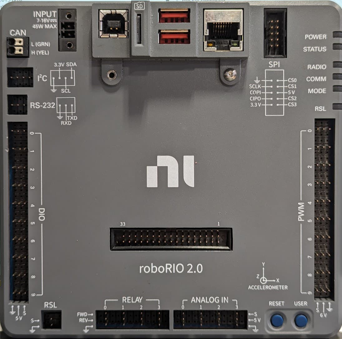
Pin Configuration and Descriptions
Power and Communication Ports
| Pin/Port Name | Description |
|---|---|
| Power Input | Accepts 7V to 16V DC input for powering the unit |
| USB Host Port | Connects to USB devices (e.g., flash drives) |
| USB Device Port | For programming and debugging via PC |
| Ethernet Port | For network communication and remote control |
| CAN Port | For communication with CAN-enabled devices |
Digital and Analog I/O
| Pin/Port Name | Description |
|---|---|
| Digital I/O (DIO) | 10 configurable pins for digital input/output |
| PWM Outputs | 10 pins for controlling motors and servos |
| Analog Inputs | 4 pins for reading analog sensor data |
| SPI/I2C/UART | Multi-purpose communication interfaces |
Usage Instructions
How to Use the RoboRio 2.0 in a Circuit
Powering the RoboRio 2.0:
- Connect a DC power source (7V to 16V) to the power input terminals. Ensure proper polarity to avoid damage.
- Use a regulated power supply for consistent performance.
Connecting Sensors and Actuators:
- Use the Digital I/O (DIO) pins for digital sensors or switches.
- Connect analog sensors to the Analog Input pins.
- Attach motors or servos to the PWM output pins.
Programming the RoboRio 2.0:
- Install the required software development tools (e.g., LabVIEW, WPILib for Java/C++).
- Connect the RoboRio 2.0 to your PC via the USB Device Port or Ethernet.
- Deploy your code to the RoboRio 2.0 using the selected programming environment.
Communication with Other Devices:
- Use the CAN port for communication with CAN-enabled motor controllers or sensors.
- Utilize the SPI, I2C, or UART interfaces for additional peripherals.
Important Considerations and Best Practices
- Power Supply: Always use a stable and regulated power source to prevent voltage fluctuations.
- Wiring: Double-check all connections to avoid short circuits or incorrect wiring.
- Firmware Updates: Keep the RoboRio 2.0 firmware up to date for optimal performance and compatibility.
- Cooling: Ensure adequate ventilation to prevent overheating during extended use.
- Safety: Disconnect power before making any wiring changes to avoid electrical hazards.
Example Code for Arduino UNO Integration
Although the RoboRio 2.0 is a standalone controller, it can communicate with an Arduino UNO via I2C. Below is an example of Arduino code for sending data to the RoboRio 2.0:
#include <Wire.h> // Include the Wire library for I2C communication

#define ROBO_RIO_ADDRESS 0x08 // I2C address of the RoboRio 2.0

void setup() {
  Wire.begin(); // Initialize I2C communication
  Serial.begin(9600); // Initialize serial communication for debugging
}

void loop() {
  Wire.beginTransmission(ROBO_RIO_ADDRESS); // Start communication with RoboRio
  Wire.write("Hello, RoboRio!"); // Send a message to the RoboRio
  Wire.endTransmission(); // End the transmission

  Serial.println("Message sent to RoboRio."); // Debug message
  delay(1000); // Wait for 1 second before sending the next message
}
Note: Ensure that the RoboRio 2.0 is configured to receive I2C data and that the I2C address matches the one defined in the Arduino code.
Troubleshooting and FAQs
Common Issues and Solutions
RoboRio 2.0 Not Powering On
- Cause: Insufficient or incorrect power supply.
- Solution: Verify the power source voltage (7V to 16V) and check the polarity of the connections.
Unable to Deploy Code
- Cause: Incorrect connection or missing drivers.
- Solution: Ensure the RoboRio 2.0 is connected via USB or Ethernet and that the required drivers are installed.
Sensors Not Responding
- Cause: Incorrect wiring or configuration.
- Solution: Double-check the sensor connections and ensure the correct pins are used in the code.
Overheating
- Cause: Prolonged use in a poorly ventilated environment.
- Solution: Improve ventilation or add a cooling fan to the setup.
FAQs
Q: Can the RoboRio 2.0 be programmed with Python?
A: Yes, the RoboRio 2.0 supports Python via libraries such as RobotPy.Q: Is the RoboRio 2.0 compatible with older FRC components?
A: Yes, it is designed to work with most FRC components, including motor controllers and sensors.Q: How do I reset the RoboRio 2.0?
A: Press and hold the reset button on the unit for a few seconds to perform a soft reset.Q: Can I use the RoboRio 2.0 for non-robotics applications?
A: Yes, its versatile design makes it suitable for various embedded control applications.