Cirkit Designer Logo
Cirkit Designer
Your all-in-one circuit design IDE
Home / 
Component Documentation

How to Use Adafruit MPM3610 5V: Examples, Pinouts, and Specs

Image of Adafruit MPM3610 5V
Cirkit Designer LogoDesign with Adafruit MPM3610 5V in Cirkit Designer

Introduction

The Adafruit MPM3610 5V is a compact, high-efficiency, synchronous buck converter module designed to step down a higher voltage to a regulated 5V output. This module is ideal for powering 5V electronics from a higher voltage source, making it perfect for battery-powered applications, portable devices, and microcontroller platforms such as the Arduino.

Explore Projects Built with Adafruit MPM3610 5V

Use Cirkit Designer to design, explore, and prototype these projects online. Some projects support real-time simulation. Click "Open Project" to start designing instantly!
Arduino Mega 2560-Controlled Servo System with Flex Sensor Feedback and Li-ion Battery Power
Image of Robot Hand: A project utilizing Adafruit MPM3610 5V in a practical application
This circuit appears to be a servo control system with an Arduino Mega 2560 as the central microcontroller. It uses multiple 18650 Li-ion batteries connected in series for power, which is regulated to 5V by an Adafruit MPM3610 5V buck converter to drive several servos. The servos are controlled by PWM signals from the Arduino, and there are flex resistors connected to analog inputs, likely for sensing bending or flexing as input to the system.
Cirkit Designer LogoOpen Project in Cirkit Designer
Arduino Pro Mini and HC-05 Bluetooth Controlled Coreless Motor Clock with MPU-6050 Feedback
Image of drone: A project utilizing Adafruit MPM3610 5V in a practical application
This is a motion-controlled device with wireless capabilities, powered by a LiPo battery with voltage regulation. It uses an Arduino Pro Mini to process MPU-6050 sensor data and control coreless motors via MOSFETs, interfacing with an external device through an HC-05 Bluetooth module.
Cirkit Designer LogoOpen Project in Cirkit Designer
Battery-Powered Raspberry Pi Zero W with MPU-6050 and LCD Display
Image of Science Fair: A project utilizing Adafruit MPM3610 5V in a practical application
This circuit is a portable system powered by a 2000mAh battery, which is stepped up to 5V using a boost converter to power a Raspberry Pi Zero W. The Raspberry Pi interfaces with an MPU-6050 sensor for motion detection, an LCD TFT screen for display, and a vibration motor for haptic feedback.
Cirkit Designer LogoOpen Project in Cirkit Designer
Battery-Powered Raspberry Pi Pico GPS Tracker with Sensor Integration
Image of Copy of CanSet v1: A project utilizing Adafruit MPM3610 5V in a practical application
This circuit is a data acquisition and communication system powered by a LiPoly battery and managed by a Raspberry Pi Pico. It includes sensors (BMP280, MPU9250) for environmental data, a GPS module for location tracking, an SD card for data storage, and a WLR089-CanSAT for wireless communication. The TP4056 module handles battery charging, and a toggle switch controls power distribution.
Cirkit Designer LogoOpen Project in Cirkit Designer

Explore Projects Built with Adafruit MPM3610 5V

Use Cirkit Designer to design, explore, and prototype these projects online. Some projects support real-time simulation. Click "Open Project" to start designing instantly!
Image of Robot Hand: A project utilizing Adafruit MPM3610 5V in a practical application
Arduino Mega 2560-Controlled Servo System with Flex Sensor Feedback and Li-ion Battery Power
This circuit appears to be a servo control system with an Arduino Mega 2560 as the central microcontroller. It uses multiple 18650 Li-ion batteries connected in series for power, which is regulated to 5V by an Adafruit MPM3610 5V buck converter to drive several servos. The servos are controlled by PWM signals from the Arduino, and there are flex resistors connected to analog inputs, likely for sensing bending or flexing as input to the system.
Cirkit Designer LogoOpen Project in Cirkit Designer
Image of drone: A project utilizing Adafruit MPM3610 5V in a practical application
Arduino Pro Mini and HC-05 Bluetooth Controlled Coreless Motor Clock with MPU-6050 Feedback
This is a motion-controlled device with wireless capabilities, powered by a LiPo battery with voltage regulation. It uses an Arduino Pro Mini to process MPU-6050 sensor data and control coreless motors via MOSFETs, interfacing with an external device through an HC-05 Bluetooth module.
Cirkit Designer LogoOpen Project in Cirkit Designer
Image of Science Fair: A project utilizing Adafruit MPM3610 5V in a practical application
Battery-Powered Raspberry Pi Zero W with MPU-6050 and LCD Display
This circuit is a portable system powered by a 2000mAh battery, which is stepped up to 5V using a boost converter to power a Raspberry Pi Zero W. The Raspberry Pi interfaces with an MPU-6050 sensor for motion detection, an LCD TFT screen for display, and a vibration motor for haptic feedback.
Cirkit Designer LogoOpen Project in Cirkit Designer
Image of Copy of CanSet v1: A project utilizing Adafruit MPM3610 5V in a practical application
Battery-Powered Raspberry Pi Pico GPS Tracker with Sensor Integration
This circuit is a data acquisition and communication system powered by a LiPoly battery and managed by a Raspberry Pi Pico. It includes sensors (BMP280, MPU9250) for environmental data, a GPS module for location tracking, an SD card for data storage, and a WLR089-CanSAT for wireless communication. The TP4056 module handles battery charging, and a toggle switch controls power distribution.
Cirkit Designer LogoOpen Project in Cirkit Designer

Common Applications

  • Powering 5V USB devices
  • Supplying 5V to microcontrollers and sensors
  • Battery-powered projects requiring a stable 5V supply
  • IoT devices with power efficiency needs

Technical Specifications

Key Technical Details

  • Input Voltage: 6V to 21V
  • Output Voltage: 5V DC
  • Maximum Output Current: 1.2A
  • Efficiency: Up to 95%
  • Quiescent Current: 0.5mA typical
  • Switching Frequency: 2MHz
  • Operating Temperature: -40°C to +85°C

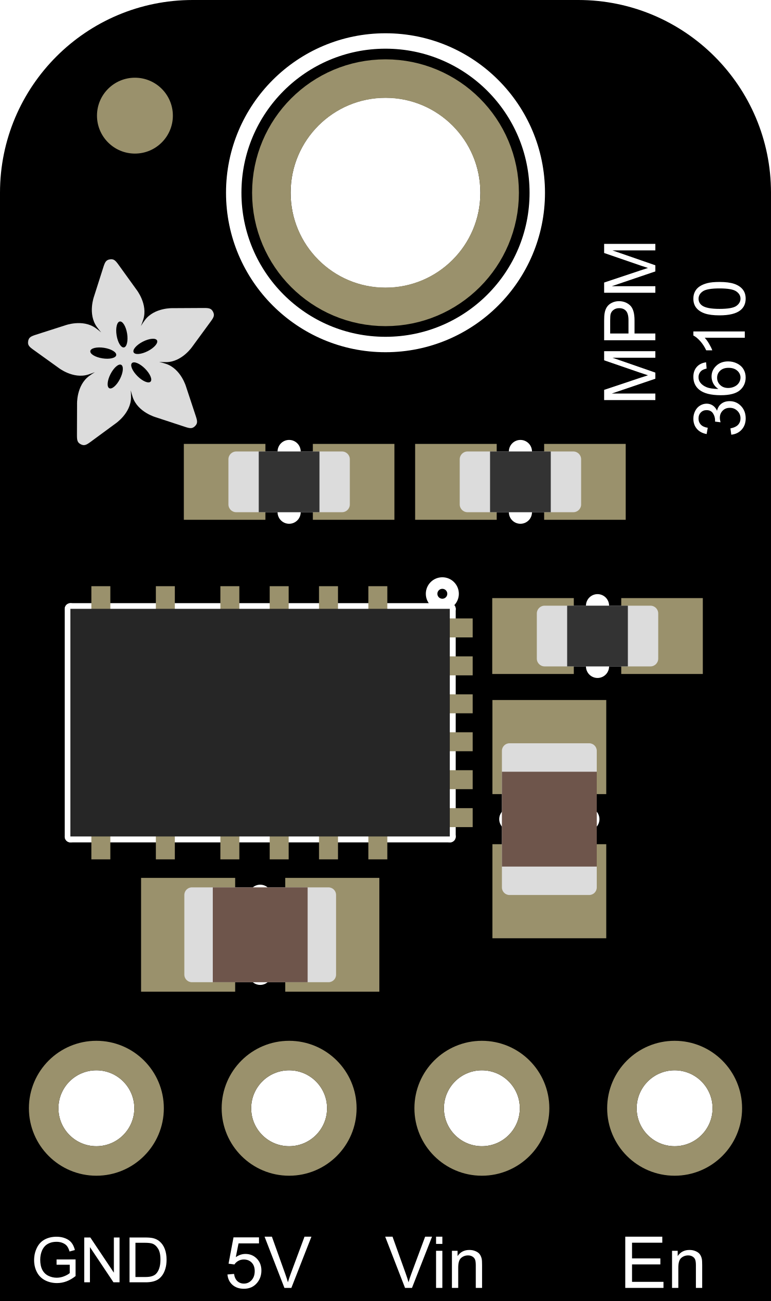
Pin Configuration and Descriptions

Pin Number Name Description
1 VIN Input voltage (6V to 21V)
2 GND Ground connection
3 VOUT Regulated 5V output
4 EN Enable pin (pull high to enable)

Usage Instructions

How to Use the Component in a Circuit

  1. Connect the input voltage (6V to 21V) to the VIN pin.
  2. Connect the ground from your power supply to the GND pin.
  3. The VOUT pin will provide a regulated 5V output.
  4. Optionally, connect the EN pin to a digital output of a microcontroller to enable or disable the converter programmatically.

Important Considerations and Best Practices

  • Ensure that the input voltage does not exceed 21V to prevent damage.
  • Do not exceed the maximum output current of 1.2A.
  • Place the module close to the power input of your circuit to minimize losses.
  • Use decoupling capacitors close to the power inputs of sensitive components.
  • If using the EN pin, ensure it is pulled high to enable the module or low to disable it.

Example Code for Arduino UNO

// Example code to enable and disable the Adafruit MPM3610 5V module using an Arduino UNO

const int enablePin = 7; // Connect the EN pin of the module to digital pin 7

void setup() {
  pinMode(enablePin, OUTPUT); // Set the enable pin as an output
}

void loop() {
  digitalWrite(enablePin, HIGH); // Enable the MPM3610 module
  delay(5000);                  // Wait for 5 seconds

  digitalWrite(enablePin, LOW);  // Disable the MPM3610 module
  delay(5000);                  // Wait for 5 seconds
}

Troubleshooting and FAQs

Common Issues

  • No Output Voltage: Ensure that the input voltage is within the specified range and that all connections are secure.
  • Output Voltage Drops Under Load: Check if the current draw is within the module's limit of 1.2A.
  • Module Overheating: Reduce the load if the module is too hot or improve ventilation/cooling.

Solutions and Tips for Troubleshooting

  • Verify that the input voltage is stable and within the specified range.
  • Check for any shorts or poor connections in the circuit.
  • Ensure that the EN pin is properly controlled; it should be high for normal operation.
  • Use a multimeter to check the output voltage and current.

FAQs

Q: Can I use the MPM3610 to power a 5V USB device? A: Yes, as long as the device's current draw is below 1.2A.

Q: What should I do if the module is not outputting 5V? A: Check the input voltage, connections, and ensure the EN pin is pulled high.

Q: Is it possible to adjust the output voltage? A: No, the output voltage is fixed at 5V.

Q: Can I use multiple MPM3610 modules in parallel to increase the current output? A: It is not recommended to parallel buck converters due to potential current sharing issues.

For further assistance, contact Adafruit support or refer to the community forums for additional help.