How to Use AMS1117-3.3V: Examples, Pinouts, and Specs
AMS1117-3.3V Linear Voltage Regulator Documentation
1. Introduction
The AMS1117-3.3V is a low dropout (LDO) linear voltage regulator designed to provide a stable and regulated output voltage of 3.3V. It is capable of delivering up to 1A of output current, making it suitable for a wide range of low-power electronic applications. The AMS1117-3.3V features built-in thermal shutdown and current limiting to protect the device and connected circuits from damage due to overheating or overcurrent conditions.
Common Applications
- Powering microcontrollers (e.g., Arduino, ESP8266, ESP32)
- Voltage regulation for sensors and modules
- Battery-powered devices
- Low-noise analog circuits
- General-purpose 3.3V power supply for embedded systems
2. Technical Specifications
The following table outlines the key technical specifications of the AMS1117-3.3V:
| Parameter | Value |
|---|---|
| Output Voltage | 3.3V |
| Input Voltage Range | 4.5V to 15V |
| Maximum Output Current | 1A |
| Dropout Voltage | 1.1V (at 1A load) |
| Quiescent Current | 5mA (typical) |
| Operating Temperature Range | -40°C to +125°C |
| Thermal Shutdown | Yes |
| Current Limiting | Yes |
| Package Types | SOT-223, TO-252, TO-263 |
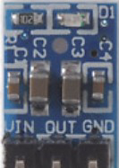
Pin Configuration and Descriptions
The AMS1117-3.3V is typically available in a SOT-223 package. The pinout is as follows:
| Pin Number | Pin Name | Description |
|---|---|---|
| 1 | GND | Ground connection |
| 2 | VOUT | Regulated 3.3V output |
| 3 | VIN | Input voltage (4.5V to 15V) |
| Tab | GND | Ground (connected to the heatsink for thermal dissipation) |
3. Usage Instructions
How to Use the AMS1117-3.3V in a Circuit
- Input Voltage: Connect a DC voltage source (4.5V to 15V) to the VIN pin. Ensure the input voltage is at least 1.1V higher than the desired output voltage (3.3V) to maintain proper regulation.
- Output Voltage: Connect the load to the VOUT pin. The output voltage will be regulated to 3.3V.
- Ground Connection: Connect the GND pin to the ground of the circuit.
- Capacitors: For stable operation, use the following capacitors:
- A 10µF electrolytic capacitor on the input (VIN to GND).
- A 10µF electrolytic capacitor on the output (VOUT to GND). These capacitors help filter noise and improve stability.
Circuit Diagram
Below is a simple circuit diagram for using the AMS1117-3.3V:
   +4.5V to 15V
        │
        │
       [10µF]  <-- Input Capacitor
        │
        │
       VIN
        │
   AMS1117-3.3V
        │
       VOUT
        │
       [10µF]  <-- Output Capacitor
        │
       +3.3V
        │
       Load
        │
       GND
        │
       GND
Important Considerations
- Heat Dissipation: The AMS1117-3.3V can generate heat when operating at high currents. Ensure proper heat dissipation by using a heatsink or adequate PCB copper area connected to the ground tab.
- Input Voltage: Avoid exceeding the maximum input voltage of 15V to prevent damage to the regulator.
- Load Current: Do not exceed the maximum output current of 1A. If the load requires more current, consider using a higher-rated regulator.
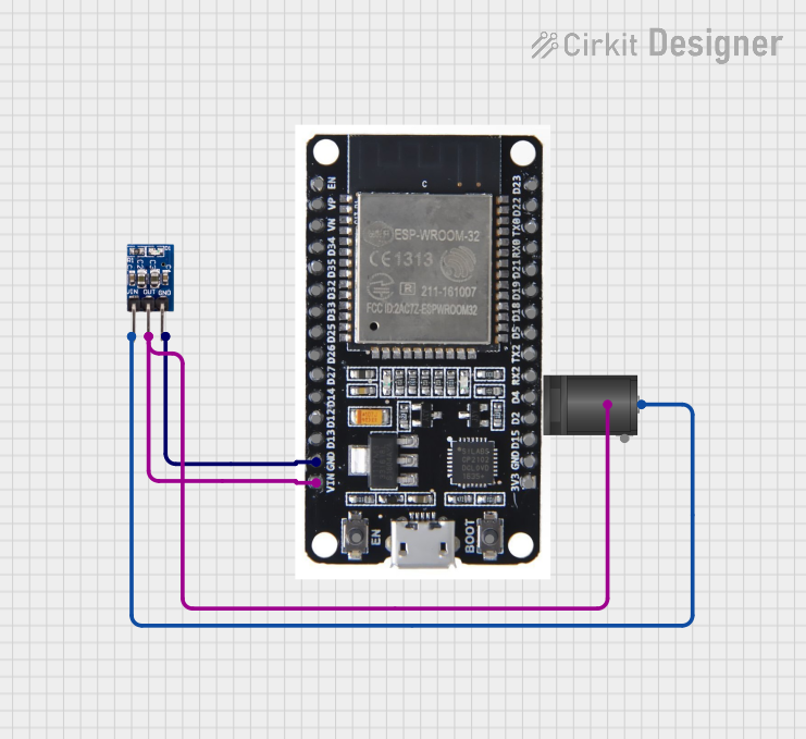
4. Example: Using AMS1117-3.3V with Arduino UNO
The AMS1117-3.3V can be used to power 3.3V devices from the 5V output of an Arduino UNO. Below is an example circuit and code to demonstrate its usage.
Circuit Setup
- Connect the 5V pin of the Arduino UNO to the VIN pin of the AMS1117-3.3V.
- Connect the GND pin of the Arduino UNO to the GND pin of the AMS1117-3.3V.
- Connect the VOUT pin of the AMS1117-3.3V to the 3.3V device (e.g., a sensor or module).
Example Code
Here is an example Arduino sketch to read data from a 3.3V sensor (e.g., a DHT11 temperature and humidity sensor):
#include <DHT.h>

// Define the DHT sensor type and pin
#define DHTPIN 2       // DHT sensor connected to digital pin 2
#define DHTTYPE DHT11  // DHT11 sensor type

DHT dht(DHTPIN, DHTTYPE);

void setup() {
  Serial.begin(9600);  // Initialize serial communication
  dht.begin();         // Initialize the DHT sensor
  Serial.println("DHT11 Sensor Test");
}

void loop() {
  delay(2000);  // Wait 2 seconds between readings

  // Read temperature and humidity from the DHT sensor
  float humidity = dht.readHumidity();
  float temperature = dht.readTemperature();

  // Check if the readings are valid
  if (isnan(humidity) || isnan(temperature)) {
    Serial.println("Failed to read from DHT sensor!");
    return;
  }

  // Print the readings to the Serial Monitor
  Serial.print("Humidity: ");
  Serial.print(humidity);
  Serial.print("%  Temperature: ");
  Serial.print(temperature);
  Serial.println("°C");
}
5. Troubleshooting and FAQs
Common Issues and Solutions
| Issue | Possible Cause | Solution |
|---|---|---|
| Output voltage is not 3.3V | Insufficient input voltage | Ensure VIN is at least 4.5V and 1.1V above VOUT. |
| Regulator overheating | Excessive load current or poor heat dissipation | Reduce load current or improve heat dissipation. |
| Circuit instability or noise | Missing or incorrect capacitors | Add 10µF capacitors to both input and output. |
| No output voltage | Incorrect wiring or damaged regulator | Verify connections and replace the regulator. |
FAQs
Can I use the AMS1117-3.3V with a 3.7V Li-ion battery?
- No, the input voltage must be at least 4.5V for proper operation.
What is the maximum current the AMS1117-3.3V can handle?
- The AMS1117-3.3V can handle up to 1A of output current, provided proper heat dissipation is ensured.
Can I use ceramic capacitors instead of electrolytic capacitors?
- Yes, but ensure the capacitance value is sufficient (e.g., 10µF) and the voltage rating is appropriate.
Is the AMS1117-3.3V suitable for powering high-frequency circuits?
- The AMS1117-3.3V is suitable for low-noise applications, but for high-frequency circuits, additional filtering may be required.
This concludes the documentation for the AMS1117-3.3V linear voltage regulator. For further assistance, refer to the manufacturer's datasheet or contact technical support.
Explore Projects Built with AMS1117-3.3V


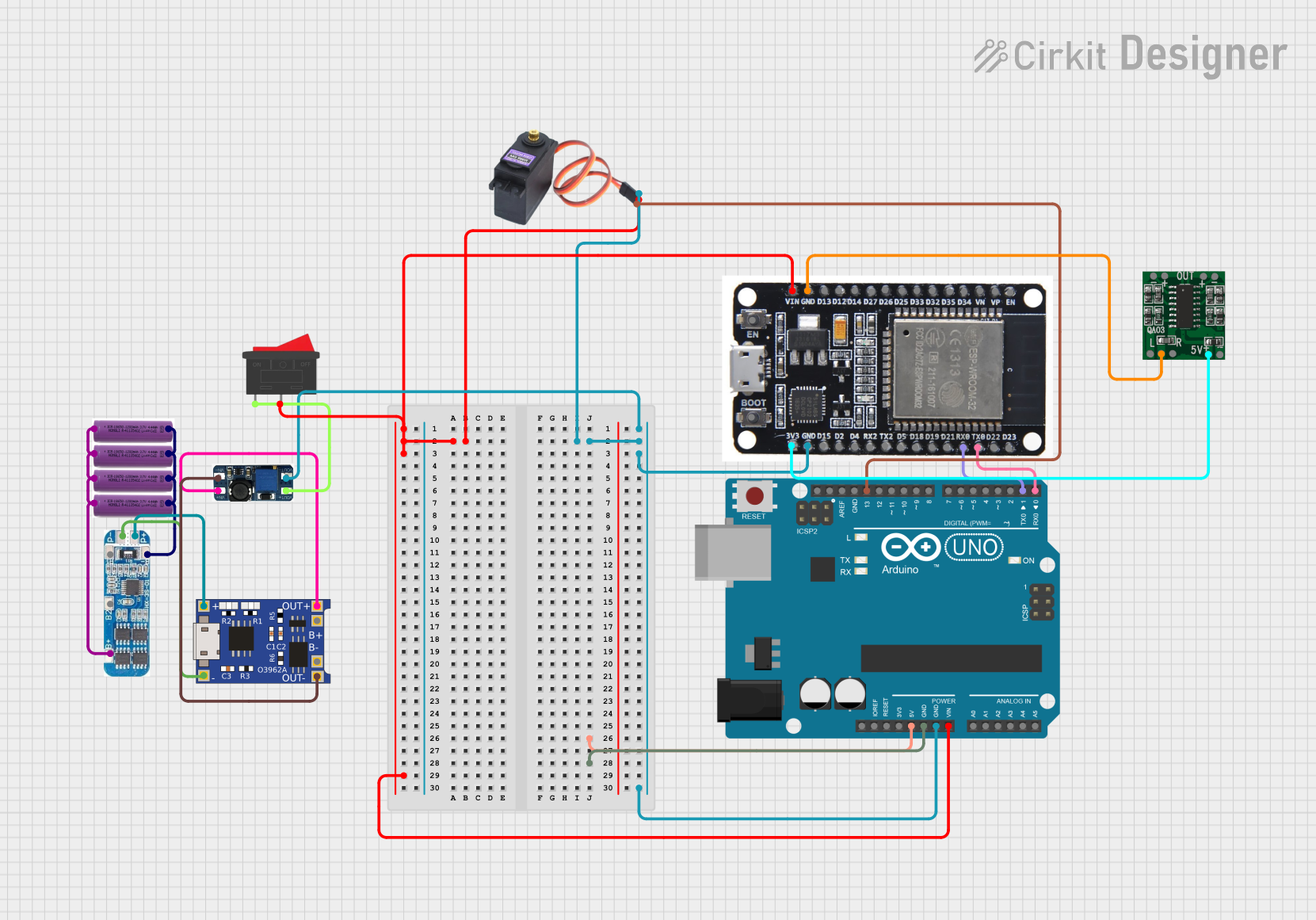
Explore Projects Built with AMS1117-3.3V