How to Use MKE-S11 IR Infrared Obstacle Avoidance Sensor: Examples, Pinouts, and Specs
Introduction
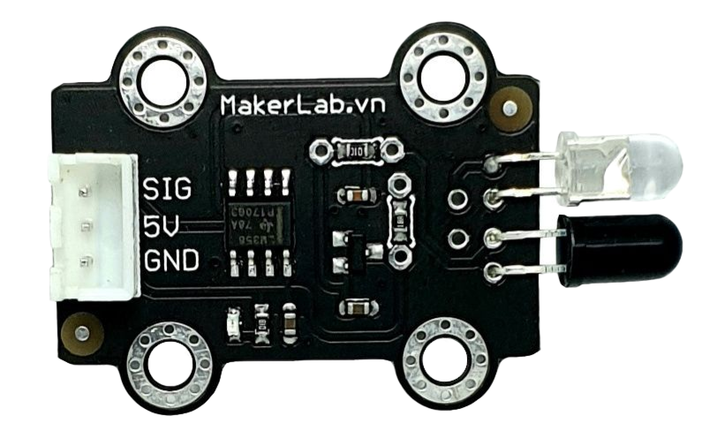
The MKE-S11 IR Infrared Obstacle Avoidance Sensor is an electronic device designed to detect the presence of obstacles through infrared reflection. It is widely used in robotics, automation projects, and interactive installations to prevent collisions by sensing objects in the path of a moving device. The sensor operates by emitting an infrared signal and then detecting the reflected signal from nearby objects.
Explore Projects Built with MKE-S11 IR Infrared Obstacle Avoidance Sensor

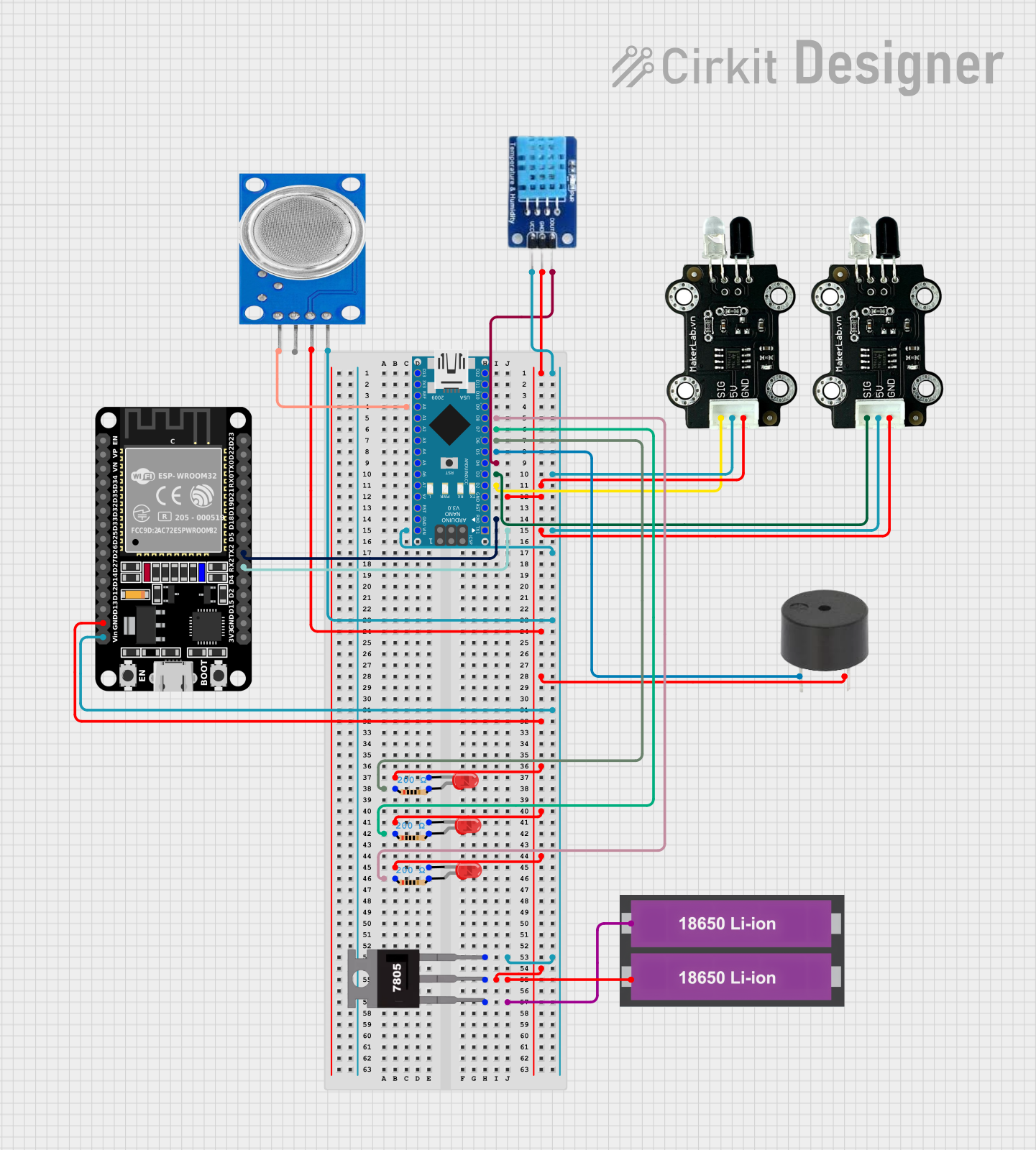
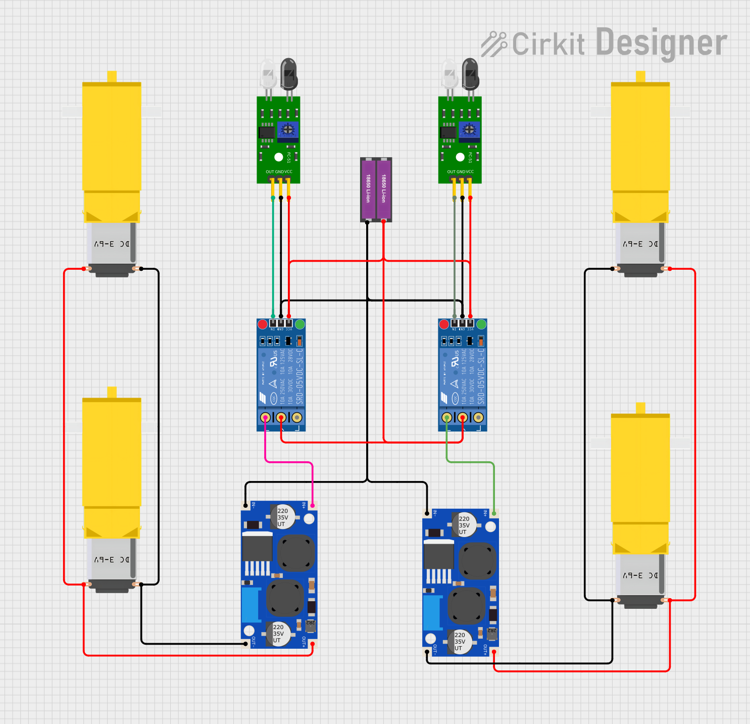

Explore Projects Built with MKE-S11 IR Infrared Obstacle Avoidance Sensor
Common Applications and Use Cases
- Robotics: obstacle detection and avoidance
- Automated guided vehicles (AGVs): path navigation
- Interactive installations: user presence detection
- Security systems: intrusion detection
Technical Specifications
Key Technical Details
- Operating Voltage: 3.3V to 5V DC
- Current Consumption: 20mA
- Output Type: Digital signal (0V or 5V)
- Detection Range: 2cm to 30cm (adjustable)
- Detection Angle: 35°
- Ambient Light Resistance: Good
- Operating Temperature: -10°C to +50°C
Pin Configuration and Descriptions
| Pin Number | Pin Name | Description |
|---|---|---|
| 1 | VCC | Power supply (3.3V to 5V DC) |
| 2 | GND | Ground |
| 3 | OUT | Digital output signal (LOW when detected) |
Usage Instructions
How to Use the Component in a Circuit
- Power Connection: Connect the VCC pin to a 3.3V or 5V power supply and the GND pin to the ground of your circuit.
- Output Connection: Connect the OUT pin to a digital input pin on your microcontroller (e.g., Arduino UNO).
- Adjustment: Use the onboard potentiometer to adjust the detection range as per your requirement.
Important Considerations and Best Practices
- Ensure that the sensor is not exposed to direct sunlight or strong artificial light sources to prevent false detections.
- Avoid placing the sensor in an environment with high dust or moisture levels.
- The sensor should be mounted securely to minimize vibrations that could affect its readings.
- Keep the sensor's lens clean and unobstructed.
Example Code for Arduino UNO
// Define the pin connected to the sensor's output
const int obstacleSensorPin = 2;

void setup() {
  // Initialize the sensor's output pin as an input
  pinMode(obstacleSensorPin, INPUT);
  // Begin serial communication at a baud rate of 9600
  Serial.begin(9600);
}

void loop() {
  // Read the sensor's output
  int sensorValue = digitalRead(obstacleSensorPin);
  // If the sensor's output is LOW, an obstacle is detected
  if (sensorValue == LOW) {
    Serial.println("Obstacle detected!");
  } else {
    Serial.println("Path is clear.");
  }
  // Wait for 200 milliseconds before the next reading
  delay(200);
}
Troubleshooting and FAQs
Common Issues Users Might Face
- Sensor Always Indicates an Obstacle: Check if the detection range is properly adjusted using the onboard potentiometer. Ensure that the sensor is not facing a permanent obstacle or highly reflective surface.
- Intermittent False Readings: Verify that the sensor is not exposed to direct or strong artificial light. Check for loose connections and ensure that the power supply is stable.
- No Output Signal: Confirm that the sensor is correctly powered and that the OUT pin is connected to the correct digital input on the microcontroller.
Solutions and Tips for Troubleshooting
- Adjust the potentiometer slowly while monitoring the output to find the optimal detection range.
- Use a multimeter to check for proper voltage levels at the VCC and GND pins.
- If using long wires, consider using shielded cables to reduce electrical noise.
FAQs
Q: Can the sensor detect transparent objects? A: The sensor may have difficulty detecting transparent or highly reflective objects due to the nature of infrared light.
Q: Is it possible to use multiple sensors in one project? A: Yes, multiple sensors can be used but ensure they are spaced adequately to prevent cross-talk and interference.
Q: How can I extend the detection range of the sensor? A: The detection range is fixed and can only be adjusted within the specified limits using the onboard potentiometer. For longer ranges, consider using a different model or type of sensor.
Remember to always follow safety guidelines when working with electronic components and ensure that all connections are secure before powering your circuit.