How to Use 4 Channel Relay Module: Examples, Pinouts, and Specs
Introduction
The 4 Channel Relay Module is an electronic component designed to control up to four separate high-power devices using low-voltage control signals. It acts as an interface between microcontrollers (e.g., Arduino, Raspberry Pi) and high-voltage devices, enabling safe and efficient switching. The module typically features opto-isolation to protect the control circuit from high-voltage spikes, ensuring safety and reliability.
Explore Projects Built with 4 Channel Relay Module


Explore Projects Built with 4 Channel Relay Module
Common Applications and Use Cases
- Home Automation: Controlling lights, fans, and other household appliances.
- Industrial Control: Managing motors, pumps, and other industrial equipment.
- Robotics: Switching actuators or other high-power components.
- IoT Projects: Enabling remote control of devices via the internet.
- Prototyping: Testing and developing circuits that require high-power switching.
Technical Specifications
The following are the key technical details of the 4 Channel Relay Module:
| Parameter | Specification |
|---|---|
| Operating Voltage | 5V DC |
| Trigger Voltage | 3.3V to 5V (compatible with most microcontrollers) |
| Relay Type | SPDT (Single Pole Double Throw) |
| Maximum Load (AC) | 250V AC @ 10A |
| Maximum Load (DC) | 30V DC @ 10A |
| Isolation Method | Opto-isolator |
| Dimensions | ~75mm x 55mm x 20mm |
| Indicator LEDs | One LED per channel (indicates relay state) |
| Control Signal Logic | Active Low |
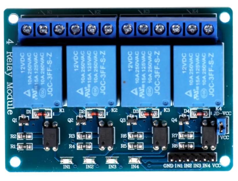
Pin Configuration and Descriptions
The 4 Channel Relay Module has the following pin layout:
Input Pins (Control Side)
| Pin Name | Description |
|---|---|
| VCC | Power supply for the module (5V DC). |
| GND | Ground connection. |
| IN1 | Control signal for Relay 1 (Active Low). |
| IN2 | Control signal for Relay 2 (Active Low). |
| IN3 | Control signal for Relay 3 (Active Low). |
| IN4 | Control signal for Relay 4 (Active Low). |
Output Pins (Relay Side)
Each relay has three output terminals:
| Terminal | Description |
|---|---|
| NO (Normally Open) | Open circuit when the relay is inactive. Closes when activated. |
| NC (Normally Closed) | Closed circuit when the relay is inactive. Opens when activated. |
| COM (Common) | Common terminal for the relay. |
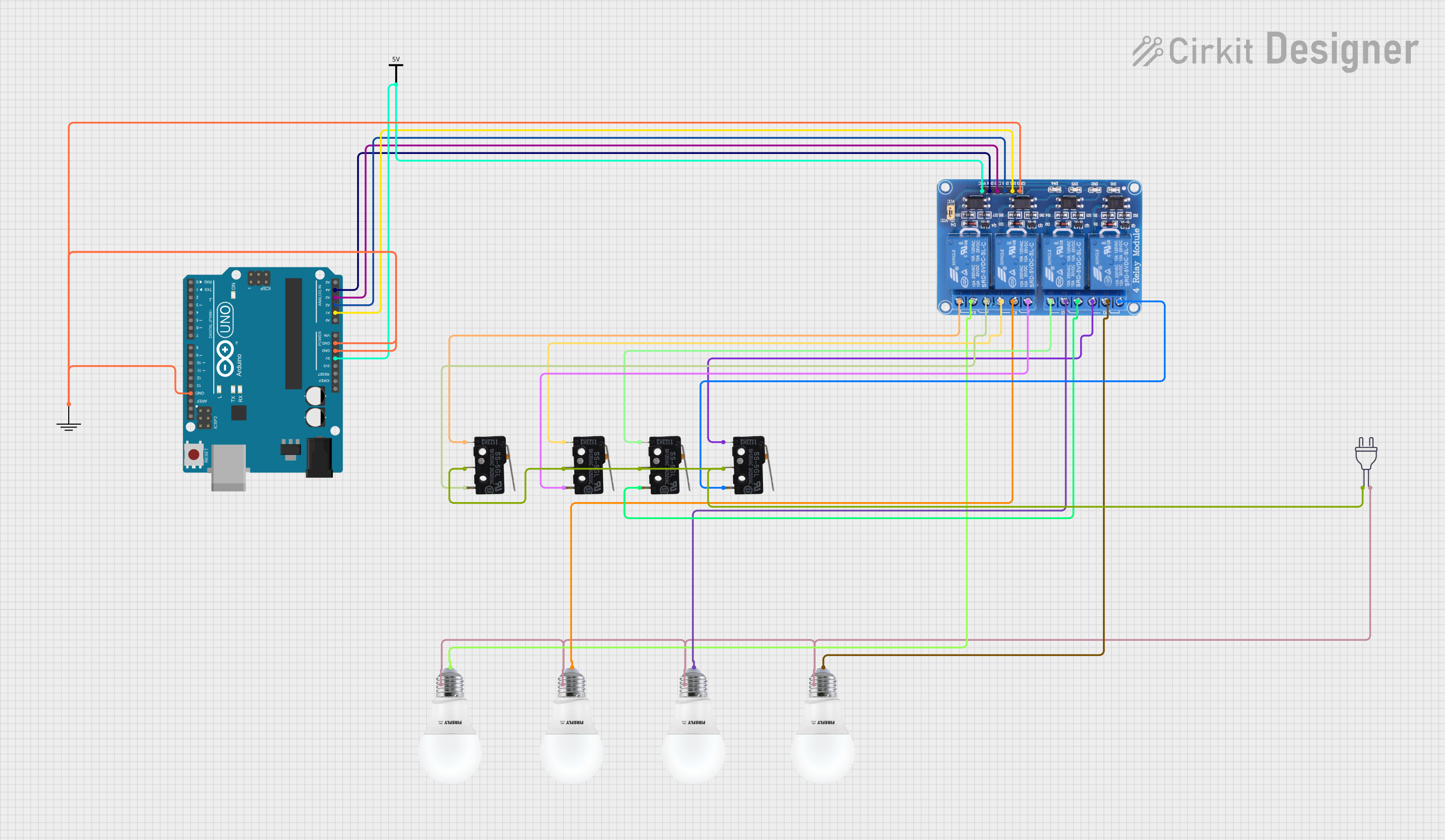
Usage Instructions
How to Use the 4 Channel Relay Module in a Circuit
- Power the Module: Connect the VCC pin to a 5V DC power source and the GND pin to ground.
- Connect Control Signals: Use digital output pins from a microcontroller (e.g., Arduino) to connect to the IN1, IN2, IN3, and IN4 pins. Ensure the control signals are active low.
- Connect the Load: For each relay, connect the high-power device to the NO, NC, and COM terminals as required:
- For devices that should turn on when the relay is activated, use the NO and COM terminals.
- For devices that should turn off when the relay is activated, use the NC and COM terminals.
- Write Control Code: Program the microcontroller to send signals to the IN pins to activate or deactivate the relays.
Important Considerations and Best Practices
- Power Supply: Ensure the module is powered with a stable 5V DC supply. Avoid exceeding the voltage rating.
- Isolation: Use opto-isolation to protect the microcontroller from high-voltage spikes.
- Load Ratings: Do not exceed the maximum load ratings (250V AC @ 10A or 30V DC @ 10A) to prevent damage.
- Active Low Logic: Remember that the relays are triggered by a LOW signal on the IN pins.
- Safety: Always disconnect power when wiring high-voltage devices to the relay module.
Example Code for Arduino UNO
Below is an example code snippet to control the 4 Channel Relay Module using an Arduino UNO:
// Define relay control pins
#define RELAY1 2  // Pin connected to IN1
#define RELAY2 3  // Pin connected to IN2
#define RELAY3 4  // Pin connected to IN3
#define RELAY4 5  // Pin connected to IN4

void setup() {
  // Set relay pins as outputs
  pinMode(RELAY1, OUTPUT);
  pinMode(RELAY2, OUTPUT);
  pinMode(RELAY3, OUTPUT);
  pinMode(RELAY4, OUTPUT);

  // Initialize all relays to OFF (HIGH state)
  digitalWrite(RELAY1, HIGH);
  digitalWrite(RELAY2, HIGH);
  digitalWrite(RELAY3, HIGH);
  digitalWrite(RELAY4, HIGH);
}

void loop() {
  // Example: Turn on Relay 1 for 2 seconds, then turn it off
  digitalWrite(RELAY1, LOW);  // Activate Relay 1
  delay(2000);                // Wait for 2 seconds
  digitalWrite(RELAY1, HIGH); // Deactivate Relay 1
  delay(2000);                // Wait for 2 seconds

  // Repeat similar logic for other relays as needed
}
Troubleshooting and FAQs
Common Issues and Solutions
Relays Not Activating:
- Cause: Insufficient power supply or incorrect wiring.
- Solution: Ensure the module is powered with 5V DC and the GND is connected properly.
Microcontroller Resetting When Relays Activate:
- Cause: Voltage spikes or insufficient power supply to the microcontroller.
- Solution: Use a separate power supply for the relay module and microcontroller. Add a flyback diode across the relay coil if not already present.
LED Indicators Not Lighting Up:
- Cause: Faulty module or incorrect control signals.
- Solution: Verify the control signals are active low and check the module for damage.
Load Not Switching Properly:
- Cause: Incorrect wiring of the load to the relay terminals.
- Solution: Double-check the connections to the NO, NC, and COM terminals.
FAQs
Q: Can I use a 3.3V microcontroller with this module?
A: Yes, the module is compatible with 3.3V control signals, but ensure the power supply to the module is 5V.Q: Can I control DC motors with this module?
A: Yes, as long as the motor's voltage and current ratings are within the relay's specifications.Q: Is it safe to use this module with 220V AC appliances?
A: Yes, but ensure proper insulation and follow safety precautions when working with high voltages.Q: Can I use fewer than 4 relays?
A: Yes, you can use only the required number of relays and leave the unused channels unconnected.