How to Use +/- 30 inH2O Differential Pressure Sensor: Examples, Pinouts, and Specs
Introduction
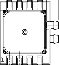
The Amphenol DLH-L30D-E1BD-C-NAV8 is a high-precision differential pressure sensor designed to measure the pressure difference between two points. With a measurement range of +/- 30 inches of water column (inH2O), this sensor is ideal for applications requiring accurate and reliable pressure monitoring. Its robust design and high sensitivity make it suitable for use in HVAC systems, fluid dynamics, industrial process control, and medical devices.
This sensor provides an analog output proportional to the pressure difference, enabling seamless integration into a variety of systems. Its compact form factor and high accuracy make it a versatile choice for both commercial and industrial applications.
Explore Projects Built with +/- 30 inH2O Differential Pressure Sensor
Explore Projects Built with +/- 30 inH2O Differential Pressure Sensor
Technical Specifications
Below are the key technical details of the DLH-L30D-E1BD-C-NAV8 differential pressure sensor:
General Specifications
| Parameter | Value |
|---|---|
| Manufacturer | Amphenol |
| Part Number | DLH-L30D-E1BD-C-NAV8 |
| Pressure Range | +/- 30 inH2O |
| Output Type | Analog Voltage |
| Supply Voltage (Vcc) | 5 V DC |
| Output Voltage Range | 0.5 V to 4.5 V |
| Accuracy | ±0.25% Full Scale (typical) |
| Operating Temperature Range | -20°C to +85°C |
| Pressure Port Configuration | Dual Port (Differential) |
| Media Compatibility | Dry air and non-corrosive gases |
Pin Configuration
The sensor features a standard 8-pin configuration. The pinout and descriptions are as follows:
| Pin Number | Name | Description |
|---|---|---|
| 1 | Vcc | Power supply input (5 V DC) |
| 2 | GND | Ground |
| 3 | Vout | Analog output voltage proportional to pressure |
| 4 | NC | Not connected |
| 5 | NC | Not connected |
| 6 | NC | Not connected |
| 7 | NC | Not connected |
| 8 | NC | Not connected |
Note: Pins labeled "NC" are not connected and should be left unconnected in the circuit.
Usage Instructions
How to Use the Sensor in a Circuit
- Power Supply: Connect the Vcc pin to a regulated 5 V DC power source and the GND pin to the ground of your circuit.
- Pressure Ports: Attach the two pressure ports to the points where the pressure difference is to be measured. Ensure the media is compatible (dry air or non-corrosive gases).
- The positive port measures the higher pressure.
- The negative port measures the lower pressure.
- Output Signal: The Vout pin provides an analog voltage proportional to the pressure difference. The output voltage ranges from 0.5 V (minimum pressure) to 4.5 V (maximum pressure).
Important Considerations
- Calibration: The sensor is factory-calibrated, but ensure your system accounts for the output range (0.5 V to 4.5 V) when interpreting the pressure readings.
- Media Compatibility: Use only with dry air or non-corrosive gases to avoid damage to the sensor.
- Mounting: Mount the sensor securely to minimize vibrations, which could affect accuracy.
- Filtering: If the output signal is noisy, consider adding a low-pass filter to smooth the signal.
Example: Connecting to an Arduino UNO
The sensor can be easily interfaced with an Arduino UNO to read and process the pressure data. Below is an example code snippet:
// Differential Pressure Sensor Example with Arduino UNO
// Reads the analog output from the sensor and converts it to pressure in inH2O

const int sensorPin = A0; // Connect Vout of the sensor to A0 on Arduino
const float minVoltage = 0.5; // Minimum output voltage (V)
const float maxVoltage = 4.5; // Maximum output voltage (V)
const float pressureRange = 60.0; // Total pressure range (+/- 30 inH2O)

void setup() {
  Serial.begin(9600); // Initialize serial communication
  pinMode(sensorPin, INPUT); // Set sensor pin as input
}

void loop() {
  int sensorValue = analogRead(sensorPin); // Read analog value (0-1023)
  float voltage = sensorValue * (5.0 / 1023.0); // Convert to voltage
  float pressure = ((voltage - minVoltage) / (maxVoltage - minVoltage))
                   * pressureRange - (pressureRange / 2.0);

  // Print the pressure value to the Serial Monitor
  Serial.print("Pressure: ");
  Serial.print(pressure);
  Serial.println(" inH2O");

  delay(1000); // Wait 1 second before next reading
}
Key Notes for the Code:
- Ensure the sensor's Vout pin is connected to the Arduino's A0 pin.
- The code converts the sensor's output voltage to a pressure value in inH2O.
- Adjust the
minVoltageandmaxVoltagevariables if the sensor's output range differs.
Troubleshooting and FAQs
Common Issues and Solutions
No Output Signal:
- Verify that the sensor is powered with a stable 5 V DC supply.
- Check all connections, especially the Vcc, GND, and Vout pins.
Inaccurate Readings:
- Ensure the pressure ports are securely connected and free of leaks.
- Confirm that the media is compatible (dry air or non-corrosive gases).
- Check for electrical noise and consider adding a low-pass filter if necessary.
Output Voltage Stuck at 0.5 V or 4.5 V:
- This may indicate that the pressure difference is at the sensor's minimum or maximum range. Verify the pressure conditions.
Fluctuating Readings:
- Ensure the sensor is mounted securely to minimize vibrations.
- Use a decoupling capacitor (e.g., 0.1 µF) across the power supply pins to reduce noise.
FAQs
Q: Can this sensor measure absolute pressure?
A: No, this is a differential pressure sensor. It measures the pressure difference between its two ports.
Q: What happens if the pressure exceeds the +/- 30 inH2O range?
A: The sensor's output will saturate at 0.5 V (minimum) or 4.5 V (maximum). Prolonged exposure to overpressure may damage the sensor.
Q: Can I use this sensor with liquids?
A: No, the sensor is designed for dry air and non-corrosive gases only. Using it with liquids may damage the internal components.
Q: How do I interpret a 2.5 V output?
A: A 2.5 V output corresponds to a pressure difference of 0 inH2O (no pressure difference between the ports).
By following this documentation, users can effectively integrate and troubleshoot the Amphenol DLH-L30D-E1BD-C-NAV8 differential pressure sensor in their projects.