
How to Use TP4056 + MT3608 Charger Module Step Up: Examples, Pinouts, and Specs
 Design with TP4056 + MT3608 Charger Module Step Up in Cirkit Designer
Introduction
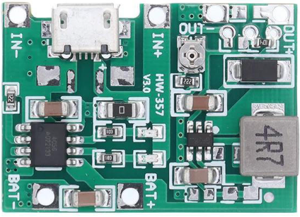
The TP4056 + MT3608 Charger Module Step Up (Manufacturer Part ID: Module-A87) is a versatile electronic module designed by Shenzhen KWM Electronics Co., Ltd. It combines two key functionalities: lithium battery charging and voltage step-up conversion. The TP4056 IC provides a constant current/constant voltage (CC/CV) charging profile for single-cell lithium-ion batteries, while the MT3608 IC boosts the output voltage to a desired level, making it suitable for powering devices requiring higher voltages.
Explore Projects Built with TP4056 + MT3608 Charger Module Step Up
 Open Project in Cirkit Designer
 Open Project in Cirkit Designer
 Open Project in Cirkit Designer
 Open Project in Cirkit Designer
Explore Projects Built with TP4056 + MT3608 Charger Module Step Up
Open Project in Cirkit DesignerOpen Project in Cirkit DesignerOpen Project in Cirkit DesignerOpen Project in Cirkit DesignerCommon Applications and Use Cases
- Charging single-cell lithium-ion or lithium-polymer batteries.
- Powering low-voltage devices with higher voltage requirements.
- Portable power banks and DIY battery-powered projects.
- Applications requiring a compact charging and voltage-boosting solution.
Technical Specifications
Key Technical Details
| Parameter | Value |
|---|---|
| Input Voltage Range | 4.5V to 5.5V (via micro-USB or IN+ pin) |
| Charging Current (TP4056) | Adjustable, up to 1A |
| Battery Type Supported | Single-cell lithium-ion/lithium-polymer |
| Output Voltage (MT3608) | Adjustable, 2V to 28V |
| Maximum Output Current (MT3608) | 2A (recommended ≤1.5A for stable operation) |
| Charging Cut-off Voltage | 4.2V ± 1% |
| Efficiency (MT3608) | Up to 93% |
| Dimensions | ~36mm x 17mm |
Pin Configuration and Descriptions
TP4056 Section
| Pin Name | Description |
|---|---|
| IN+ | Positive input for charging voltage (4.5V to 5.5V). |
| IN- | Negative input (ground) for charging voltage. |
| BAT+ | Positive terminal for the lithium battery. |
| BAT- | Negative terminal for the lithium battery. |
| OUT+ | Positive output terminal (connected to MT3608 input). |
| OUT- | Negative output terminal (connected to MT3608 input). |
MT3608 Section
| Pin Name | Description |
|---|---|
| VIN+ | Positive input voltage (connected to TP4056 OUT+). |
| VIN- | Negative input voltage (connected to TP4056 OUT-). |
| VOUT+ | Positive boosted output voltage. |
| VOUT- | Negative boosted output voltage (ground). |
| ADJ | Voltage adjustment pin (connected to a potentiometer for output tuning). |
Usage Instructions
How to Use the Component in a Circuit
- Power Input: Connect a 5V power source (e.g., USB adapter) to the micro-USB port or directly to the
IN+andIN-pins of the TP4056 section. - Battery Connection: Attach the lithium-ion battery to the
BAT+andBAT-pins. Ensure correct polarity to avoid damage. - Output Voltage Adjustment:
- Connect the load to the
VOUT+andVOUT-pins of the MT3608 section. - Use the onboard potentiometer to adjust the output voltage. Turn clockwise to increase the voltage and counterclockwise to decrease it.
- Connect the load to the
- Load Connection: Ensure the load does not exceed the maximum output current of 2A (recommended ≤1.5A for stable operation).
Important Considerations and Best Practices
- Battery Safety: Use only single-cell lithium-ion or lithium-polymer batteries. Ensure the battery has built-in protection circuitry to prevent overcharging or over-discharging.
- Heat Management: The module may heat up during operation, especially at high currents. Ensure adequate ventilation or heat dissipation.
- Voltage Adjustment: Always measure the output voltage with a multimeter before connecting sensitive devices.
- Current Limitation: Avoid exceeding the recommended current limits to prevent damage to the module or connected devices.
Example: Using with Arduino UNO
The TP4056 + MT3608 module can be used to power an Arduino UNO by boosting the battery voltage to 9V. Below is an example code to blink an LED using the Arduino UNO powered by this module:
// Example code to blink an LED using Arduino UNO
// Ensure the TP4056 + MT3608 module is set to output 9V for the Arduino UNO.

const int ledPin = 13; // Pin connected to the onboard LED

void setup() {
  pinMode(ledPin, OUTPUT); // Set the LED pin as an output
}

void loop() {
  digitalWrite(ledPin, HIGH); // Turn the LED on
  delay(1000);               // Wait for 1 second
  digitalWrite(ledPin, LOW);  // Turn the LED off
  delay(1000);               // Wait for 1 second
}
Troubleshooting and FAQs
Common Issues and Solutions
Module Overheating:
- Cause: Excessive current draw or insufficient ventilation.
- Solution: Reduce the load current or improve heat dissipation with a heatsink or fan.
Battery Not Charging:
- Cause: Incorrect battery connection or damaged battery.
- Solution: Verify the battery polarity and ensure the battery is functional.
Output Voltage Not Adjustable:
- Cause: Faulty potentiometer or incorrect wiring.
- Solution: Check the potentiometer and ensure proper connections to the MT3608 section.
No Output Voltage:
- Cause: Insufficient input voltage or damaged module.
- Solution: Ensure the input voltage is within the specified range and check for module damage.
FAQs
Q1: Can I use this module to charge multiple batteries in series?
A1: No, the TP4056 is designed for single-cell lithium-ion or lithium-polymer batteries only.
Q2: What is the maximum input voltage for the MT3608 section?
A2: The MT3608 can handle up to 28V on its input, but the TP4056 limits the input to 5.5V. Ensure the input voltage does not exceed 5.5V when using the module.
Q3: Can I use this module to power a Raspberry Pi?
A3: Yes, but ensure the output voltage is set to 5V and the current requirements of the Raspberry Pi are met.
Q4: How do I adjust the charging current?
A4: The charging current can be adjusted by replacing the onboard resistor connected to the TP4056. Refer to the TP4056 datasheet for resistor values corresponding to desired currents.
This concludes the documentation for the TP4056 + MT3608 Charger Module Step Up.