How to Use Pushbutton START: Examples, Pinouts, and Specs
Introduction
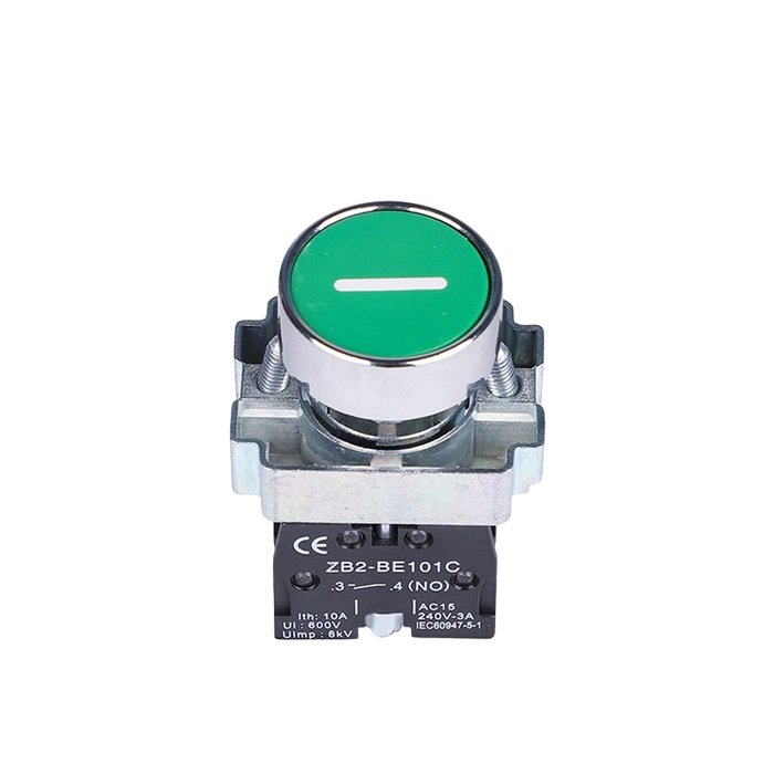
A pushbutton is a momentary switch that completes a circuit when pressed and breaks the circuit when released. It is commonly used for user input in electronic devices, such as turning devices on/off, resetting systems, or triggering specific actions. The Pushbutton START is a versatile and reliable component, ideal for applications requiring tactile user interaction.
Explore Projects Built with Pushbutton START


Explore Projects Built with Pushbutton START
Common Applications and Use Cases
- Powering on/off devices
- Resetting microcontrollers or systems
- Triggering specific functions in embedded systems
- User input in control panels or appliances
- Prototyping and testing circuits
Technical Specifications
The Pushbutton START is a simple, low-power component designed for ease of use in a variety of circuits. Below are its key specifications:
| Parameter | Value |
|---|---|
| Operating Voltage | 3.3V to 12V |
| Maximum Current Rating | 50mA |
| Contact Resistance | ≤ 50mΩ |
| Insulation Resistance | ≥ 100MΩ |
| Operating Temperature | -20°C to +70°C |
| Mechanical Durability | 100,000 cycles |
Pin Configuration and Descriptions
The Pushbutton START typically has four pins, arranged in a square configuration. The pins are internally connected in pairs, as shown below:
| Pin Number | Description |
|---|---|
| 1 and 2 | Connected internally (shorted) |
| 3 and 4 | Connected internally (shorted) |
Note: When the button is pressed, pins 1-2 are connected to pins 3-4, completing the circuit.
Usage Instructions
How to Use the Pushbutton START in a Circuit
- Identify the Pins: Use a multimeter to confirm the internal connections between pins 1-2 and 3-4.
- Connect to Circuit:
- Connect one pair of pins (e.g., 1-2) to the input signal or power source.
- Connect the other pair (e.g., 3-4) to the load or microcontroller input.
- Debounce the Signal: Pushbuttons can produce noise or "bouncing" when pressed. Use a capacitor (e.g., 0.1µF) or software debounce techniques to ensure stable operation.
- Test the Circuit: Verify that pressing the button completes the circuit and triggers the desired action.
Important Considerations and Best Practices
- Voltage and Current Ratings: Ensure the button operates within its specified voltage and current limits to avoid damage.
- Debouncing: Always implement hardware or software debouncing to prevent erratic behavior.
- Mounting: Secure the pushbutton firmly to avoid accidental disconnections during operation.
- Pull-Up or Pull-Down Resistors: When interfacing with microcontrollers, use a pull-up or pull-down resistor (typically 10kΩ) to ensure a defined logic state when the button is not pressed.
Example: Connecting to an Arduino UNO
Below is an example of how to use the Pushbutton START with an Arduino UNO to toggle an LED:
// Define pin connections
const int buttonPin = 2;  // Pushbutton connected to digital pin 2
const int ledPin = 13;    // LED connected to digital pin 13

// Variable to store button state
int buttonState = 0;

void setup() {
  pinMode(buttonPin, INPUT_PULLUP); // Set button pin as input with internal pull-up
  pinMode(ledPin, OUTPUT);         // Set LED pin as output
}

void loop() {
  // Read the state of the pushbutton
  buttonState = digitalRead(buttonPin);

  // If button is pressed (LOW due to pull-up resistor)
  if (buttonState == LOW) {
    digitalWrite(ledPin, HIGH); // Turn on the LED
  } else {
    digitalWrite(ledPin, LOW);  // Turn off the LED
  }
}
Note: The internal pull-up resistor is enabled in the code to simplify the circuit.
Troubleshooting and FAQs
Common Issues and Solutions
Button Not Responding:
- Cause: Incorrect wiring or loose connections.
- Solution: Double-check the pin connections and ensure the button is securely mounted.
Erratic Behavior (Multiple Triggers):
- Cause: Signal bouncing when the button is pressed.
- Solution: Add a capacitor (e.g., 0.1µF) across the button terminals or implement software debouncing.
Microcontroller Not Detecting Button Press:
- Cause: Missing pull-up or pull-down resistor.
- Solution: Use a 10kΩ pull-up or pull-down resistor to define the logic state when the button is not pressed.
Button Feels Stuck or Unresponsive:
- Cause: Mechanical wear or debris inside the button.
- Solution: Clean the button or replace it if it has exceeded its mechanical durability.
FAQs
Q: Can I use the Pushbutton START with a 5V system?
A: Yes, the Pushbutton START is compatible with 5V systems, as its operating voltage range is 3.3V to 12V.
Q: Do I need an external resistor for the button to work with an Arduino?
A: No, you can use the Arduino's internal pull-up resistor by configuring the pin as INPUT_PULLUP.
Q: How do I debounce the button in software?
A: You can use a delay or a state-change detection algorithm to filter out bouncing signals. For example, check the button state after a short delay (e.g., 10ms) to confirm a stable press.
Q: Can I use the Pushbutton START for high-power applications?
A: No, the Pushbutton START is designed for low-power applications with a maximum current rating of 50mA. Use a relay or transistor for high-power circuits.
By following this documentation, you can effectively integrate the Pushbutton START into your projects and troubleshoot any issues that arise.