How to Use SSR-10A: Examples, Pinouts, and Specs
Introduction
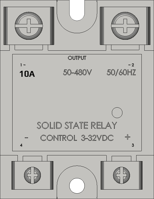
The SSR-10A is a solid-state relay (SSR) designed for switching AC loads. Unlike traditional electromechanical relays, the SSR-10A uses semiconductor components to perform switching operations, ensuring high reliability, fast response times, and silent operation. This relay is particularly well-suited for applications requiring precise control of electrical devices without mechanical wear.
Explore Projects Built with SSR-10A


Explore Projects Built with SSR-10A
Common Applications and Use Cases
- Industrial automation systems
- Heating, ventilation, and air conditioning (HVAC) systems
- Motor speed control
- Lighting control systems
- Home appliances and smart home devices
- Temperature control in ovens and furnaces
Technical Specifications
Key Technical Details
| Parameter | Value |
|---|---|
| Load Voltage Range | 24–380V AC |
| Load Current Rating | 10A |
| Control Voltage Range | 3–32V DC |
| Trigger Current | ≤7.5mA |
| On-State Voltage Drop | ≤1.6V |
| Off-State Leakage Current | ≤2mA |
| Isolation Voltage | ≥2500V AC |
| Switching Time | ≤10ms |
| Operating Temperature | -30°C to +80°C |
| Mounting Type | Panel Mount |
Pin Configuration and Descriptions
| Pin Number | Name | Description |
|---|---|---|
| 1 | Input (+) | Positive DC control signal input (3–32V DC). |
| 2 | Input (-) | Negative DC control signal input (ground). |
| 3 | Output (L1) | AC load terminal 1 (connect to one side of the AC load). |
| 4 | Output (L2) | AC load terminal 2 (connect to the other side of the AC load or AC line). |
Usage Instructions
How to Use the SSR-10A in a Circuit
Control Side (Input):
- Connect the positive control signal (3–32V DC) to the
Input (+)pin. - Connect the ground of the control signal to the
Input (-)pin. - Ensure the control voltage is within the specified range to avoid damage.
- Connect the positive control signal (3–32V DC) to the
Load Side (Output):
- Connect one terminal of the AC load to the
Output (L1)pin. - Connect the other terminal of the AC load to the
Output (L2)pin. - Ensure the load voltage and current do not exceed the SSR-10A's ratings.
- Connect one terminal of the AC load to the
Power Supply:
- Ensure the AC load voltage is within the range of 24–380V AC.
- Verify that the load current does not exceed 10A.
Mounting:
- Secure the SSR-10A to a heat sink or panel using screws to ensure proper heat dissipation.
- Use thermal paste if necessary to improve heat transfer.
Important Considerations and Best Practices
- Always use a heat sink for high-current applications to prevent overheating.
- Avoid exceeding the maximum load current (10A) to ensure long-term reliability.
- Use a snubber circuit or varistor across the load terminals to protect against voltage spikes.
- Ensure proper electrical isolation between the control and load sides.
- Double-check all connections before powering the circuit to avoid damage.
Example: Controlling an AC Lamp with Arduino UNO
Below is an example of how to use the SSR-10A to control an AC lamp with an Arduino UNO.
Circuit Connections
- Connect the Arduino's digital pin (e.g., pin 9) to the
Input (+)pin of the SSR-10A. - Connect the Arduino's ground (GND) to the
Input (-)pin of the SSR-10A. - Connect the AC lamp to the
Output (L1)andOutput (L2)pins of the SSR-10A. - Ensure the AC lamp's voltage and current are within the SSR-10A's specifications.
Arduino Code
// Example code to control an AC lamp using SSR-10A and Arduino UNO

const int ssrPin = 9; // Define the pin connected to SSR-10A Input (+)

void setup() {
  pinMode(ssrPin, OUTPUT); // Set the SSR pin as an output
}

void loop() {
  digitalWrite(ssrPin, HIGH); // Turn on the AC lamp
  delay(5000); // Keep the lamp on for 5 seconds

  digitalWrite(ssrPin, LOW); // Turn off the AC lamp
  delay(5000); // Keep the lamp off for 5 seconds
}
Notes:
- Use a proper AC-rated fuse in series with the load for safety.
- Ensure the Arduino and SSR-10A share a common ground.
Troubleshooting and FAQs
Common Issues and Solutions
| Issue | Possible Cause | Solution |
|---|---|---|
| SSR does not switch the load | Control voltage is too low or absent | Verify the control voltage is within the 3–32V DC range. |
| Load does not turn off completely | Leakage current through the SSR | Use a load with a higher minimum operating current or add a bleeder resistor. |
| SSR overheats during operation | Excessive load current or poor cooling | Ensure the load current is ≤10A and use a heat sink for proper cooling. |
| Flickering or unstable operation | Noise or insufficient control signal | Use a decoupling capacitor on the control side to stabilize the signal. |
FAQs
Can the SSR-10A switch DC loads?
- No, the SSR-10A is designed specifically for AC loads. For DC loads, use a DC-rated SSR.
Do I need a heat sink for low-current applications?
- A heat sink is not mandatory for low-current applications, but it is recommended for currents above 5A.
What happens if I exceed the maximum load current?
- Exceeding the maximum load current (10A) can damage the SSR and may cause it to fail permanently.
Can I use the SSR-10A with a PWM signal?
- The SSR-10A is not designed for high-frequency PWM signals. Use it with steady-state or low-frequency control signals.
By following this documentation, you can effectively integrate the SSR-10A into your projects and ensure reliable operation.