
How to Use ina149: Examples, Pinouts, and Specs
 Design with ina149 in Cirkit Designer
Introduction
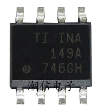
The INA149 is a precision instrumentation amplifier designed for low-power applications. It features high input impedance, low offset voltage, and low noise, making it ideal for amplifying small differential signals in the presence of large common-mode voltages. This component is particularly suited for applications requiring accurate signal amplification in environments with high common-mode voltages, such as industrial process controls, medical instrumentation, and data acquisition systems.
Explore Projects Built with ina149
 Open Project in Cirkit Designer
 Open Project in Cirkit Designer
 Open Project in Cirkit Designer
 Open Project in Cirkit Designer
Explore Projects Built with ina149

 Open Project in Cirkit Designer
 Open Project in Cirkit Designer
 Open Project in Cirkit Designer
 Open Project in Cirkit Designer
Common Applications and Use Cases
- Industrial process control systems
- Medical instrumentation
- Data acquisition systems
- High-voltage signal monitoring
- Precision measurement systems
Technical Specifications
Key Technical Details
- Supply Voltage Range: ±2.25V to ±18V (dual supply) or 4.5V to 36V (single supply)
- Input Impedance: 10 GΩ (typical)
- Common-Mode Voltage Range: ±275V
- Gain: Fixed at 1
- Offset Voltage: ±0.5 mV (maximum)
- Input Bias Current: ±25 nA (typical)
- Bandwidth: 500 kHz (typical)
- Slew Rate: 1 V/μs
- Operating Temperature Range: -40°C to +85°C
- Package Options: SOIC-8, PDIP-8
Pin Configuration and Descriptions
The INA149 is available in an 8-pin package. The pinout and descriptions are as follows:
| Pin Number | Pin Name | Description |
|---|---|---|
| 1 | -IN | Inverting input of the differential amplifier |
| 2 | +IN | Non-inverting input of the differential amplifier |
| 3 | V- | Negative power supply (ground in single-supply operation) |
| 4 | REF | Reference voltage input (sets the output voltage reference level) |
| 5 | OUT | Output of the amplifier |
| 6 | V+ | Positive power supply |
| 7 | NC | No connection (leave unconnected or connect to ground for stability) |
| 8 | NC | No connection (leave unconnected or connect to ground for stability) |
Usage Instructions
How to Use the INA149 in a Circuit
- Power Supply: Connect the INA149 to a power supply within the specified range. For dual-supply operation, connect
V+to the positive voltage andV-to the negative voltage. For single-supply operation, connectV+to the positive voltage andV-to ground. - Input Connections: Connect the differential signal to the
+INand-INpins. Ensure the common-mode voltage is within the specified range (±275V). - Reference Voltage: Use the
REFpin to set the output reference voltage. For example, connect it to ground for a ground-referenced output or to a voltage divider for a custom reference. - Output: The amplified differential signal will be available at the
OUTpin. Connect this pin to the next stage of your circuit (e.g., an ADC or microcontroller input).
Important Considerations and Best Practices
- Bypass Capacitors: Place decoupling capacitors (e.g., 0.1 μF and 10 μF) close to the power supply pins (
V+andV-) to reduce noise and improve stability. - Input Protection: If the input signal may exceed the common-mode voltage range, use external resistors or diodes to protect the inputs.
- PCB Layout: Use a clean and low-noise PCB layout. Keep input traces short and away from noisy signals to minimize interference.
- Reference Voltage: Ensure the
REFpin is properly connected to avoid unexpected output behavior.
Example: Connecting the INA149 to an Arduino UNO
The INA149 can be used to amplify a differential signal for an Arduino UNO's ADC input. Below is an example circuit and code:
Circuit
- Connect
+INand-INto the differential signal source. - Connect
REFto ground for a ground-referenced output. - Connect
OUTto an analog input pin (e.g., A0) on the Arduino UNO. - Power the INA149 with a 5V single supply (
V+to 5V,V-to ground).
Arduino Code
// INA149 Example Code for Arduino UNO
// Reads the amplified differential signal from the INA149 and prints the value

const int analogPin = A0; // Analog pin connected to INA149 OUT pin

void setup() {
  Serial.begin(9600); // Initialize serial communication at 9600 baud
}

void loop() {
  int adcValue = analogRead(analogPin); // Read the ADC value (0-1023)

  // Convert ADC value to voltage (assuming 5V reference for Arduino ADC)
  float voltage = (adcValue / 1023.0) * 5.0;

  // Print the voltage to the serial monitor
  Serial.print("Voltage: ");
  Serial.print(voltage, 3); // Print voltage with 3 decimal places
  Serial.println(" V");

  delay(500); // Wait for 500 ms before the next reading
}
Troubleshooting and FAQs
Common Issues and Solutions
No Output Signal:
- Verify that the power supply is connected and within the specified range.
- Check the input connections to ensure the differential signal is properly applied.
- Ensure the
REFpin is connected to a valid reference voltage.
Output Saturation:
- Confirm that the input common-mode voltage is within the specified range (±275V).
- Check if the output load is too high; the INA149 is designed for high-impedance loads.
High Noise in Output:
- Add bypass capacitors close to the power supply pins to reduce noise.
- Ensure the input traces are short and shielded from noisy signals.
Incorrect Output Voltage:
- Verify the
REFpin voltage. An incorrect reference voltage can shift the output. - Check for any wiring errors or loose connections.
- Verify the
FAQs
Q: Can the INA149 amplify signals with a common-mode voltage higher than the supply voltage?
A: Yes, the INA149 can handle common-mode voltages up to ±275V, even if the supply voltage is much lower. This is one of its key features.
Q: What is the maximum output current of the INA149?
A: The INA149 can source or sink up to 10 mA. Ensure the load impedance is high enough to avoid overloading the output.
Q: Can I use the INA149 with a single power supply?
A: Yes, the INA149 supports single-supply operation. Connect V+ to the positive supply voltage and V- to ground.
Q: How do I set the gain of the INA149?
A: The INA149 has a fixed gain of 1 and does not support external gain adjustment. If additional gain is required, use an external amplifier stage.