How to Use Teknic ClearCore: Examples, Pinouts, and Specs
Introduction
The Teknic ClearCore (Part ID: CLCR-4-13) is a versatile and high-performance motion controller designed for robotics, industrial automation, and other motion control applications. It is equipped with a powerful processor, multiple communication interfaces, and support for various motor types, including stepper, servo, and brushed DC motors. The ClearCore is ideal for applications requiring precise motion control, such as CNC machines, 3D printers, and robotic arms.
Explore Projects Built with Teknic ClearCore

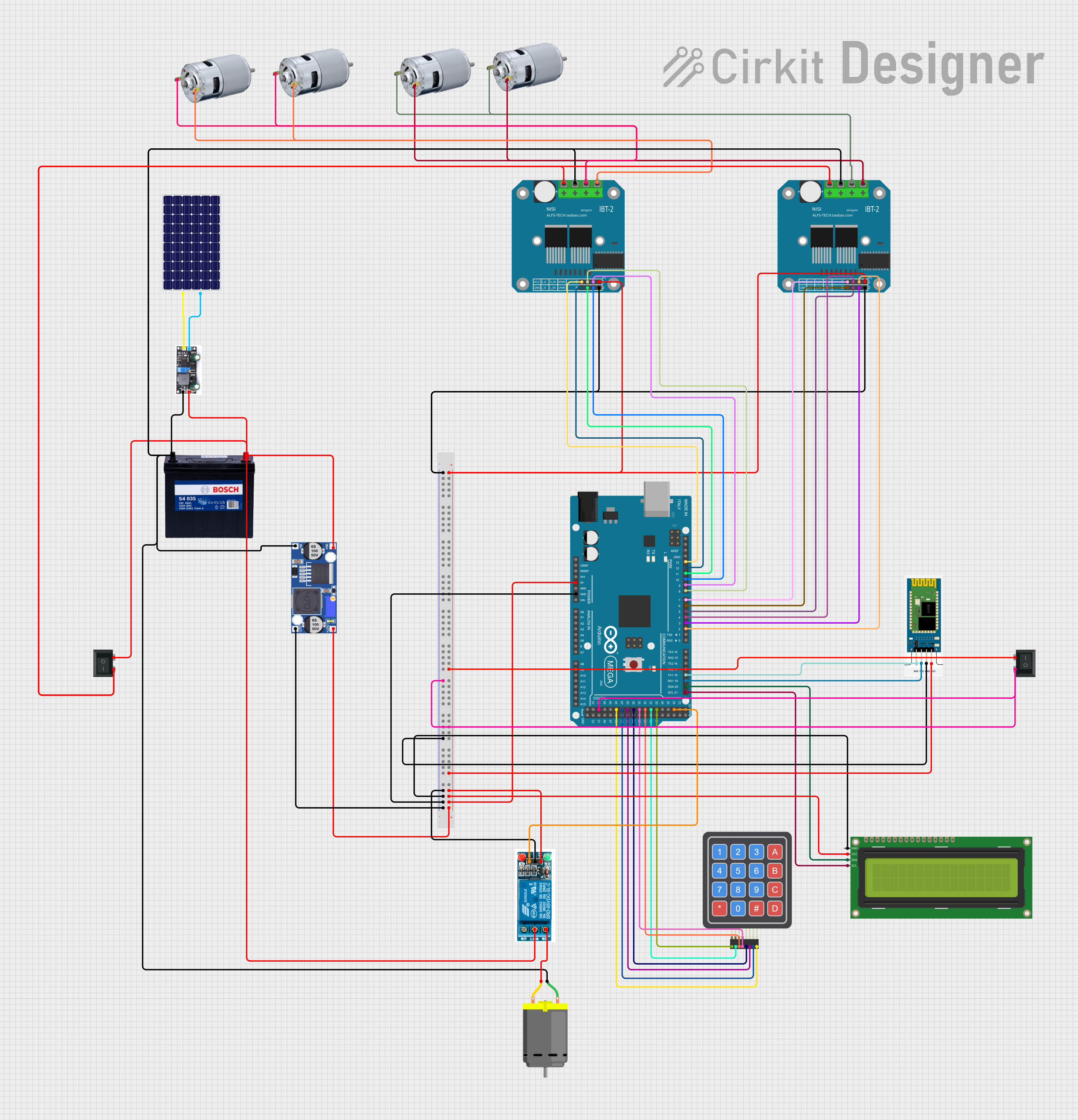
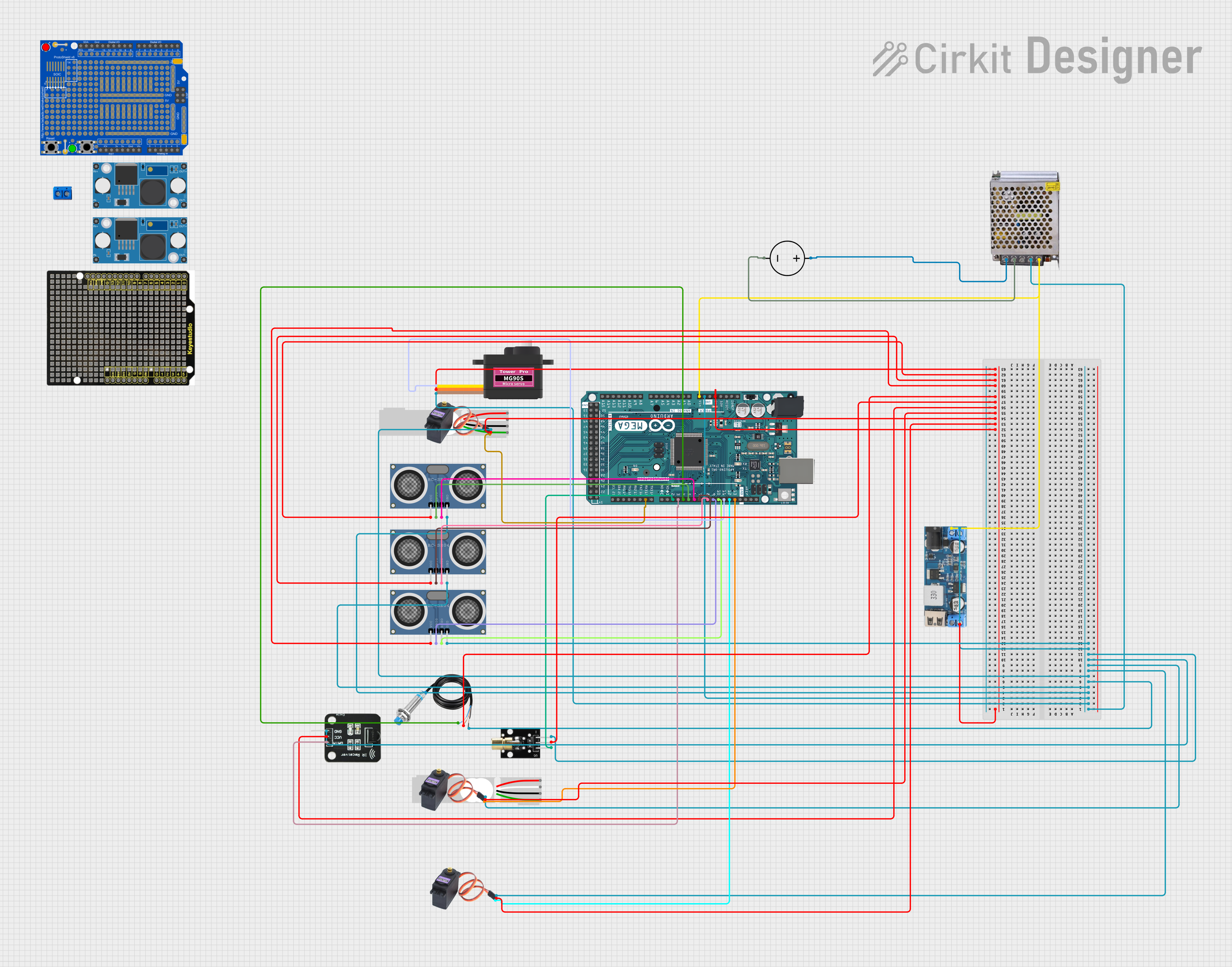
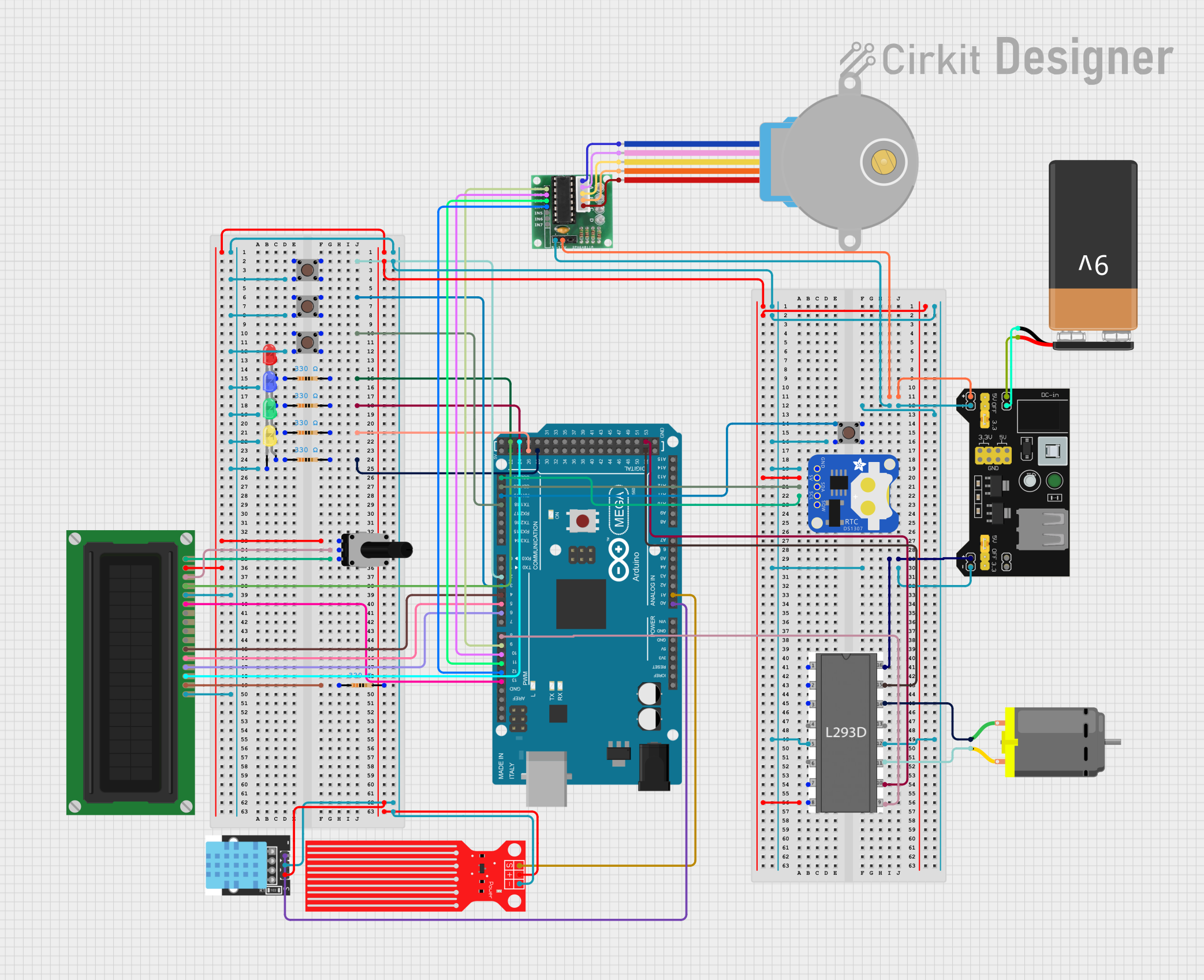
Explore Projects Built with Teknic ClearCore
Common Applications and Use Cases
- CNC machining and milling systems
- 3D printing and additive manufacturing
- Robotic arms and manipulators
- Conveyor belt systems
- Automated inspection and testing equipment
- Pick-and-place machines
Technical Specifications
Key Technical Details
| Parameter | Specification |
|---|---|
| Processor | ARM Cortex-M4, 120 MHz |
| Input Voltage Range | 12-48 V DC |
| Communication Interfaces | USB, RS-232, CAN, Ethernet |
| Motor Control Support | Stepper, Servo, Brushed DC |
| Digital I/O | 8 configurable digital I/O pins |
| Analog Inputs | 4 analog input channels (12-bit resolution) |
| PWM Outputs | 4 PWM outputs |
| Operating Temperature | -40°C to +85°C |
| Dimensions | 5.55" x 3.25" x 1.0" (141mm x 83mm x 25mm) |
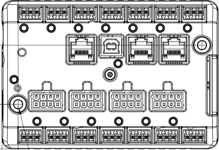
Pin Configuration and Descriptions
The ClearCore features multiple connectors for motor control, power input, and I/O. Below is a summary of the key pin configurations:
Power and Motor Connections
| Pin Name | Description |
|---|---|
| VIN | Power input (12-48 V DC) |
| GND | Ground connection |
| Motor A+ | Motor winding A positive terminal |
| Motor A- | Motor winding A negative terminal |
| Motor B+ | Motor winding B positive terminal |
| Motor B- | Motor winding B negative terminal |
Digital and Analog I/O
| Pin Name | Description |
|---|---|
| DIO1-DIO8 | Configurable digital I/O pins |
| AIN1-AIN4 | Analog input channels (12-bit resolution) |
| PWM1-PWM4 | PWM output channels |
Communication Interfaces
| Pin Name | Description |
|---|---|
| USB | USB interface for programming and control |
| RS-232 TX/RX | RS-232 communication interface |
| CAN H/L | CAN bus communication interface |
| Ethernet | Ethernet interface for network connectivity |
Usage Instructions
How to Use the Teknic ClearCore in a Circuit
- Power Connection: Connect a DC power supply (12-48 V) to the VIN and GND pins. Ensure the power supply can provide sufficient current for the connected motor(s).
- Motor Connection: Connect the motor windings to the appropriate motor terminals (A+, A-, B+, B-). Verify the motor type is supported by the ClearCore.
- I/O Configuration: Use the digital I/O pins (DIO1-DIO8) for input/output operations, such as reading sensors or controlling external devices. Analog inputs (AIN1-AIN4) can be used for reading sensor data.
- Communication Setup: Connect the ClearCore to a PC or other controller using USB, RS-232, CAN, or Ethernet, depending on your application requirements.
- Programming: Use the ClearCore API and development tools provided by Teknic to write and upload control programs. The API supports C++ and provides functions for motor control, I/O management, and communication.
Important Considerations and Best Practices
- Power Supply: Ensure the power supply voltage and current ratings match the requirements of the ClearCore and connected motors.
- Heat Dissipation: Operate the ClearCore in a well-ventilated environment to prevent overheating.
- Wiring: Use appropriate wire gauges for power and motor connections to minimize voltage drops and ensure reliable operation.
- Firmware Updates: Regularly check for firmware updates from Teknic to ensure optimal performance and compatibility.
Example Code for Arduino UNO Integration
The ClearCore can be controlled via serial communication from an Arduino UNO. Below is an example of sending commands to the ClearCore using the RS-232 interface:
#include <SoftwareSerial.h>

// Define RS-232 communication pins
#define RX_PIN 10  // Arduino RX pin connected to ClearCore TX
#define TX_PIN 11  // Arduino TX pin connected to ClearCore RX

// Create a SoftwareSerial object for RS-232 communication
SoftwareSerial clearCoreSerial(RX_PIN, TX_PIN);

void setup() {
  // Initialize serial communication with ClearCore
  clearCoreSerial.begin(9600); // Set baud rate to match ClearCore settings
  Serial.begin(9600);          // For debugging via Serial Monitor

  // Send initialization command to ClearCore
  clearCoreSerial.println("INIT"); // Replace with actual ClearCore command
  Serial.println("Sent INIT command to ClearCore");
}

void loop() {
  // Example: Send a motor control command to ClearCore
  clearCoreSerial.println("MOTOR_START"); // Replace with actual command
  Serial.println("Sent MOTOR_START command to ClearCore");

  delay(1000); // Wait for 1 second

  // Example: Stop the motor
  clearCoreSerial.println("MOTOR_STOP"); // Replace with actual command
  Serial.println("Sent MOTOR_STOP command to ClearCore");

  delay(1000); // Wait for 1 second
}
Note: Replace "INIT", "MOTOR_START", and "MOTOR_STOP" with actual commands supported by the ClearCore API.
Troubleshooting and FAQs
Common Issues and Solutions
No Response from ClearCore:
- Cause: Incorrect communication settings or wiring.
- Solution: Verify the baud rate, communication protocol, and wiring connections. Ensure the ClearCore is powered on.
Motor Not Moving:
- Cause: Incorrect motor wiring or configuration.
- Solution: Double-check motor connections and ensure the motor type is supported. Verify the control program is sending the correct commands.
Overheating:
- Cause: Insufficient ventilation or excessive load.
- Solution: Improve airflow around the ClearCore and reduce the motor load if possible.
Analog Input Not Reading Correctly:
- Cause: Incorrect voltage levels or wiring.
- Solution: Ensure the input voltage is within the supported range (0-3.3 V) and check the wiring.
FAQs
Q: Can the ClearCore control multiple motors simultaneously?
- A: Yes, the ClearCore supports controlling multiple motors, depending on the configuration and available I/O.
Q: Is the ClearCore compatible with third-party motor drivers?
- A: Yes, the ClearCore can interface with third-party motor drivers via its digital and PWM outputs.
Q: What programming languages are supported for ClearCore development?
- A: The ClearCore API supports C++ for programming and control.
Q: How do I update the firmware on the ClearCore?
- A: Use the firmware update tool provided by Teknic. Refer to the official documentation for detailed instructions.