How to Use ePaper Driver Board for Seeed Studio XIAO V2: Examples, Pinouts, and Specs
Introduction
The ePaper Driver Board for Seeed Studio XIAO V2 is a specialized interface board designed to drive ePaper displays. It enables low-power, high-contrast visual output, making it ideal for applications requiring minimal energy consumption and excellent readability in various lighting conditions. This driver board is tailored for seamless integration with the Seeed Studio XIAO V2 microcontroller, providing a compact and efficient solution for ePaper-based projects.
Explore Projects Built with ePaper Driver Board for Seeed Studio XIAO V2

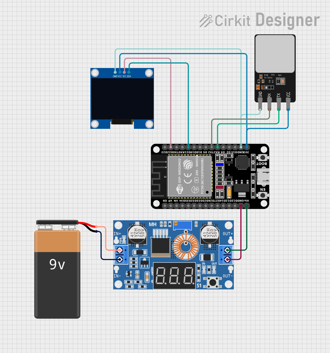


Explore Projects Built with ePaper Driver Board for Seeed Studio XIAO V2
Common Applications and Use Cases
- IoT Devices: Displaying sensor data, notifications, or status updates.
- Wearable Electronics: Low-power displays for smartwatches or fitness trackers.
- E-Readers: Compact ePaper solutions for text-based applications.
- Home Automation: Energy-efficient display panels for smart home systems.
- Prototyping: Rapid development of ePaper-based projects with the Seeed Studio XIAO V2.
Technical Specifications
The ePaper Driver Board is designed to work seamlessly with ePaper displays and the Seeed Studio XIAO V2. Below are the key technical details:
Key Technical Details
- Input Voltage: 3.3V (powered directly from the Seeed Studio XIAO V2).
- Communication Interface: SPI (Serial Peripheral Interface).
- Supported ePaper Displays: Compatible with a range of ePaper displays (e.g., 1.54", 2.13", 2.9").
- Power Consumption: Ultra-low power during operation; near-zero power in idle mode.
- Operating Temperature: -20°C to 70°C.
- Dimensions: Compact form factor designed to fit with the Seeed Studio XIAO V2.
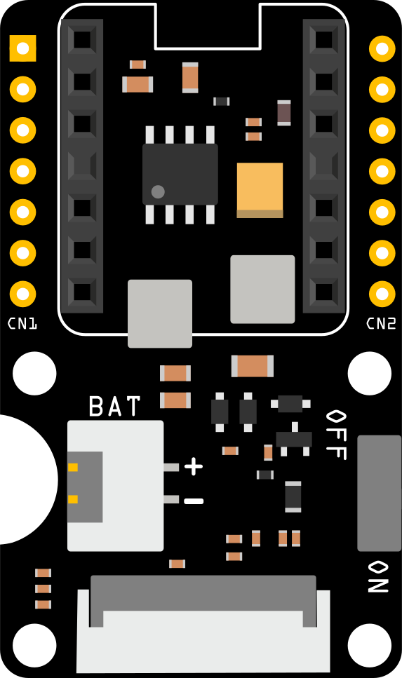
Pin Configuration and Descriptions
The ePaper Driver Board connects to the Seeed Studio XIAO V2 via its pin headers. Below is the pin configuration:
| Pin Name | Description | XIAO V2 Pin |
|---|---|---|
| VCC | Power supply (3.3V) | 3.3V |
| GND | Ground | GND |
| DIN | SPI data input (MOSI) | D10 |
| CLK | SPI clock | D9 |
| CS | Chip select | D8 |
| DC | Data/command control | D7 |
| RST | Reset signal | D6 |
| BUSY | Busy status signal (output) | D5 |
Usage Instructions
How to Use the Component in a Circuit
Connect the Driver Board to the XIAO V2:
- Align the pin headers of the ePaper Driver Board with the corresponding pins on the Seeed Studio XIAO V2.
- Ensure proper orientation to avoid incorrect connections.
Connect the ePaper Display:
- Attach the ePaper display to the connector on the driver board. Ensure the display is compatible with the driver board.
Power the Circuit:
- Supply 3.3V to the XIAO V2, which will power the driver board and the ePaper display.
Program the XIAO V2:
- Use the Arduino IDE or another compatible development environment to upload code to the XIAO V2.
Important Considerations and Best Practices
- Voltage Compatibility: Ensure the ePaper display operates at 3.3V to avoid damage.
- SPI Configuration: Configure the SPI interface correctly in your code to match the driver board's requirements.
- Refresh Rate: ePaper displays have a slower refresh rate compared to LCDs. Avoid frequent updates to minimize ghosting and power consumption.
- Handle with Care: ePaper displays are fragile. Avoid bending or applying pressure to the screen.
Example Code for Arduino UNO (Compatible with XIAO V2)
Below is an example code snippet to initialize and display text on an ePaper display using the driver board:
#include <GxEPD2_BW.h> // Include the ePaper library

// Define the ePaper display type and size
GxEPD2_BW<GxEPD2_213, GxEPD2_213::HEIGHT> display(GxEPD2_213(/*CS=*/8, /*DC=*/7, /*RST=*/6, /*BUSY=*/5));

void setup() {
  // Initialize serial communication for debugging
  Serial.begin(115200);
  Serial.println("Initializing ePaper Display...");

  // Initialize the ePaper display
  display.init();
  display.setRotation(1); // Set display orientation

  // Clear the display
  display.fillScreen(GxEPD_WHITE);
  display.display();

  // Display text
  display.setTextColor(GxEPD_BLACK);
  display.setCursor(10, 20); // Set text position
  display.setTextSize(2);    // Set text size
  display.print("Hello, ePaper!");
  display.display();         // Update the display
}

void loop() {
  // ePaper displays do not require continuous refreshing
  // Leave the loop empty or add additional logic as needed
}
Troubleshooting and FAQs
Common Issues Users Might Face
Display Not Turning On:
- Cause: Incorrect wiring or insufficient power supply.
- Solution: Double-check all connections and ensure the XIAO V2 is powered with 3.3V.
No Output on the Display:
- Cause: Incorrect SPI configuration or incompatible ePaper display.
- Solution: Verify the SPI pins and ensure the display is supported by the driver board.
Ghosting or Artifacts on the Display:
- Cause: Frequent updates or improper refresh commands.
- Solution: Minimize updates and use the library's refresh functions correctly.
Busy Pin Stuck High:
- Cause: The ePaper display is not initializing properly.
- Solution: Check the reset (RST) pin connection and ensure the display is compatible.
Solutions and Tips for Troubleshooting
- Use a multimeter to verify voltage levels at the driver board and display.
- Test the SPI communication using a simple sketch to ensure data is being transmitted.
- Refer to the ePaper display's datasheet for specific initialization and refresh requirements.
- Update the ePaper library to the latest version for improved compatibility and bug fixes.