How to Use Encoder AS5048A : Examples, Pinouts, and Specs
Introduction
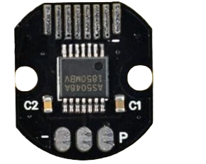
The AS5048A is a high-resolution magnetic rotary encoder designed to provide precise absolute position feedback. With a 14-bit resolution, it can measure angular positions with exceptional accuracy. The encoder communicates via SPI or PWM interfaces, making it versatile and easy to integrate into a wide range of systems. Its robust design and high precision make it ideal for applications in robotics, automation, motor control, and industrial machinery.
Explore Projects Built with Encoder AS5048A

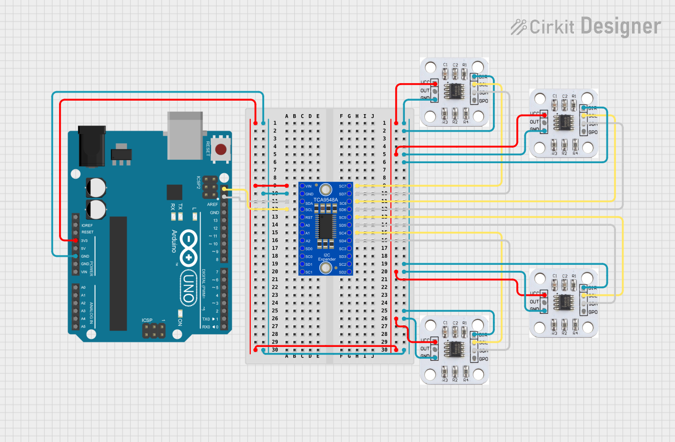
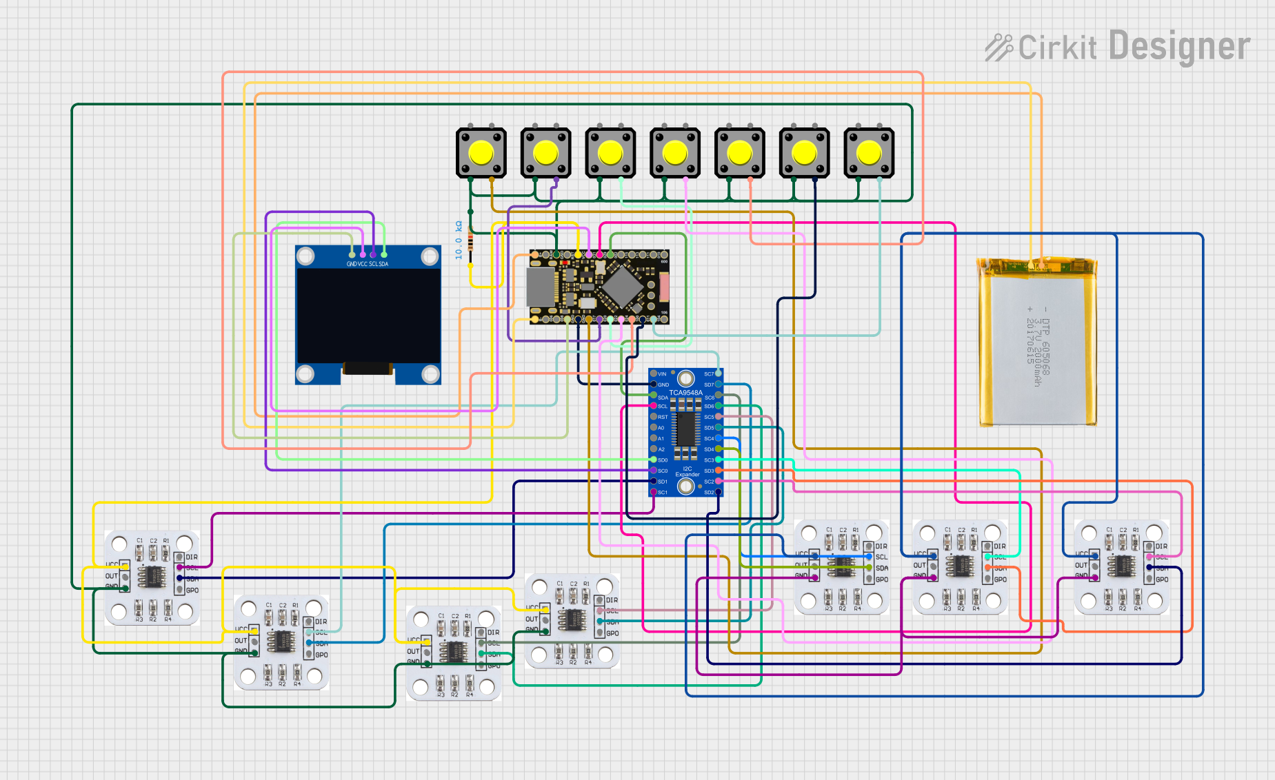

Explore Projects Built with Encoder AS5048A
Common Applications
- Robotic arm joint position sensing
- Motor shaft position feedback
- Industrial automation systems
- Precision control in CNC machines
- Servo motor feedback loops
Technical Specifications
Key Technical Details
| Parameter | Value |
|---|---|
| Resolution | 14-bit (16,384 steps per revolution) |
| Interface | SPI or PWM |
| Supply Voltage | 3.3V to 5.5V |
| Operating Current | 12 mA (typical) |
| Maximum Speed | 30,000 RPM |
| Operating Temperature | -40°C to +150°C |
| Magnetic Field Strength | 30 mT to 70 mT |
| Package | TSSOP-14 |
Pin Configuration
The AS5048A comes in a 14-pin TSSOP package. Below is the pinout and description:
| Pin Number | Pin Name | Description |
|---|---|---|
| 1 | VDD | Positive supply voltage (3.3V to 5.5V) |
| 2 | VSS | Ground |
| 3 | CSn | Chip Select (active low) for SPI communication |
| 4 | CLK | SPI Clock input |
| 5 | MISO | SPI Master-In-Slave-Out (data output) |
| 6 | MOSI | SPI Master-Out-Slave-In (data input) |
| 7 | PWM | PWM output for position feedback |
| 8-14 | NC | Not connected |
Usage Instructions
Using the AS5048A in a Circuit
- Power Supply: Connect the VDD pin to a 3.3V or 5V power source and the VSS pin to ground.
- SPI Communication:
- Connect the
CSn,CLK,MISO, andMOSIpins to the corresponding SPI pins on your microcontroller. - Ensure the
CSnpin is pulled low to enable communication.
- Connect the
- PWM Output:
- If using the PWM interface, connect the
PWMpin to a microcontroller's input pin capable of reading PWM signals.
- If using the PWM interface, connect the
- Magnet Placement:
- Place a diametrically magnetized magnet (6-8 mm diameter recommended) above the encoder chip.
- Ensure the magnet is centered and within the specified distance (0.5 mm to 3 mm) for accurate readings.
Important Considerations
- Magnetic Field Strength: Ensure the magnet provides a field strength between 30 mT and 70 mT for reliable operation.
- Noise Filtering: Use decoupling capacitors (e.g., 100 nF) close to the VDD and VSS pins to reduce noise.
- SPI Clock Speed: The SPI clock frequency should not exceed 10 MHz.
- Alignment: Proper alignment of the magnet is critical for accurate position measurements.
Example Code for Arduino UNO (SPI Interface)
#include <SPI.h>

// Define SPI pins for AS5048A
const int CSn = 10; // Chip Select pin

void setup() {
  // Initialize Serial Monitor
  Serial.begin(9600);

  // Initialize SPI
  SPI.begin();
  pinMode(CSn, OUTPUT);
  digitalWrite(CSn, HIGH); // Set CSn high to disable communication
}

uint16_t readAS5048A() {
  uint16_t angle = 0;

  // Start SPI communication
  digitalWrite(CSn, LOW);

  // Send command to read angle (0xFFFF is the command for angle read)
  uint16_t command = 0xFFFF;
  uint16_t response = SPI.transfer16(command);

  // End SPI communication
  digitalWrite(CSn, HIGH);

  // Extract angle data (14-bit resolution)
  angle = response & 0x3FFF; // Mask to keep only 14 bits

  return angle;
}

void loop() {
  // Read angle from AS5048A
  uint16_t angle = readAS5048A();

  // Convert angle to degrees (0-360)
  float angleDegrees = (angle * 360.0) / 16384.0;

  // Print angle to Serial Monitor
  Serial.print("Angle: ");
  Serial.print(angleDegrees);
  Serial.println(" degrees");

  delay(100); // Delay for readability
}
Notes on the Code
- The
SPI.transfer16()function sends a 16-bit command and receives a 16-bit response. - The angle is extracted from the 14 least significant bits of the response.
- Ensure the
CSnpin is correctly configured for your setup.
Troubleshooting and FAQs
Common Issues
No Output or Incorrect Readings:
- Verify the power supply voltage (3.3V to 5.5V).
- Check the alignment and distance of the magnet.
- Ensure proper SPI connections and configurations.
Noise in Readings:
- Add decoupling capacitors near the power pins.
- Use shielded cables for SPI connections in noisy environments.
PWM Output Not Detected:
- Ensure the microcontroller pin is configured to read PWM signals.
- Verify the magnet's placement and field strength.
FAQs
Q: Can the AS5048A measure incremental positions?
A: No, the AS5048A provides absolute position feedback. For incremental measurements, you would need to calculate the difference between successive readings.
Q: What type of magnet should I use?
A: Use a diametrically magnetized magnet with a diameter of 6-8 mm and a field strength of 30 mT to 70 mT.
Q: Can I use the AS5048A with a 5V microcontroller?
A: Yes, the AS5048A supports a supply voltage range of 3.3V to 5.5V, making it compatible with 5V systems.
Q: What is the maximum distance between the magnet and the encoder?
A: The recommended distance is between 0.5 mm and 3 mm for accurate readings.
By following this documentation, you can effectively integrate the AS5048A encoder into your projects and achieve precise position feedback.