How to Use Voltage transformer: Examples, Pinouts, and Specs
Introduction
A voltage transformer is a device that converts electrical energy from one voltage level to another. It is commonly used to step up (increase) or step down (decrease) voltage in power systems. Voltage transformers are essential in electrical distribution networks, ensuring that voltage levels are appropriate for various applications, such as powering household appliances, industrial equipment, or sensitive electronic devices.
Explore Projects Built with Voltage transformer


Explore Projects Built with Voltage transformer
Common Applications and Use Cases
- Power distribution systems to step down high transmission voltages for residential or commercial use.
- Industrial machinery requiring specific voltage levels.
- Electrical isolation to protect sensitive equipment.
- Voltage regulation in renewable energy systems like solar or wind power setups.
- Testing and calibration in laboratories.
Technical Specifications
Below are the general technical specifications for a typical voltage transformer. Note that actual specifications may vary depending on the model and manufacturer.
Key Technical Details
- Input Voltage Range: 110V AC to 240V AC (varies by model)
- Output Voltage Range: 5V AC to 24V AC (or other specified levels)
- Frequency: 50Hz or 60Hz
- Power Rating: 10VA to 10kVA (depending on application)
- Efficiency: Typically 95% or higher
- Insulation Resistance: >100MΩ at 500V DC
- Operating Temperature: -20°C to 70°C
- Dielectric Strength: 2kV AC for 1 minute (varies by model)
Pin Configuration and Descriptions
The pin configuration of a voltage transformer depends on its type (e.g., step-up, step-down, or isolation transformer). Below is a general example for a single-phase transformer:
| Pin Number | Label | Description |
|---|---|---|
| 1 | Primary Live | Input live wire for the primary winding. |
| 2 | Primary Neutral | Input neutral wire for the primary winding. |
| 3 | Secondary Live | Output live wire for the secondary winding. |
| 4 | Secondary Neutral | Output neutral wire for the secondary winding. |
| 5 | Ground | Ground connection for safety and shielding. |
For three-phase transformers or specialized models, refer to the manufacturer's datasheet for detailed pinouts.
Usage Instructions
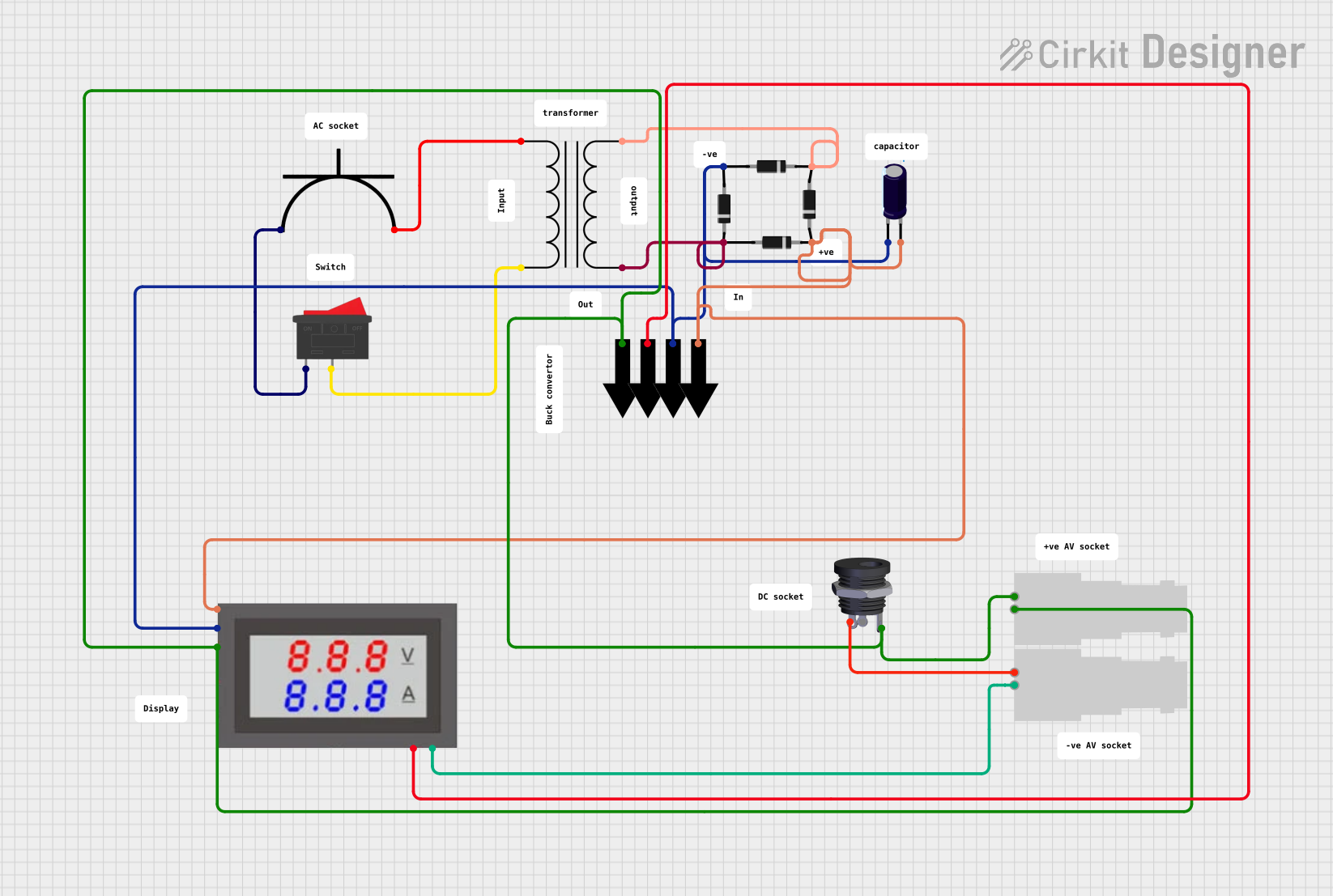
How to Use the Component in a Circuit
- Determine Voltage Requirements: Identify the input and output voltage levels required for your application.
- Connect the Primary Side:
- Connect the live and neutral wires of the input voltage source to the primary winding pins (e.g., Pin 1 and Pin 2).
- Ensure the input voltage matches the transformer's rated input voltage.
- Connect the Secondary Side:
- Connect the load to the secondary winding pins (e.g., Pin 3 and Pin 4).
- Verify that the load's voltage and current requirements match the transformer's output specifications.
- Grounding:
- Connect the ground pin (if available) to the system ground for safety.
- Power On:
- After verifying all connections, power on the transformer and measure the output voltage to ensure proper operation.
Important Considerations and Best Practices
- Overloading: Do not exceed the transformer's rated power capacity, as this can cause overheating and damage.
- Isolation: Use isolation transformers for sensitive equipment to prevent electrical noise and surges.
- Cooling: Ensure adequate ventilation or cooling for high-power transformers to prevent overheating.
- Safety: Always disconnect power before making or modifying connections.
- Testing: Use a multimeter to verify input and output voltages before connecting the load.
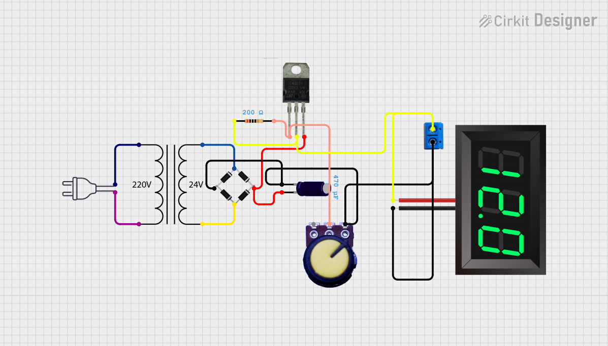
Example: Using a Voltage Transformer with an Arduino UNO
If you are using a voltage transformer to step down AC voltage for an Arduino UNO, you will need a rectifier circuit to convert AC to DC. Below is an example code snippet to read the stepped-down voltage using the Arduino's analog input:
// Example code to read voltage from a transformer using Arduino UNO
// Ensure the transformer output is rectified and stepped down to a safe DC level
// (e.g., 0-5V) before connecting to the Arduino analog pin.

const int voltagePin = A0; // Analog pin connected to the rectified transformer output
float voltage = 0.0;       // Variable to store the measured voltage

void setup() {
  Serial.begin(9600); // Initialize serial communication at 9600 baud
}

void loop() {
  int sensorValue = analogRead(voltagePin); // Read the analog input
  // Convert the analog reading (0-1023) to voltage (0-5V)
  voltage = sensorValue * (5.0 / 1023.0);

  // Print the voltage to the Serial Monitor
  Serial.print("Measured Voltage: ");
  Serial.print(voltage);
  Serial.println(" V");

  delay(1000); // Wait for 1 second before the next reading
}
Note: Ensure the transformer output is rectified and regulated to a safe DC voltage (e.g., 5V) before connecting to the Arduino.
Troubleshooting and FAQs
Common Issues Users Might Face
No Output Voltage:
- Cause: Incorrect wiring or no input voltage.
- Solution: Verify the input voltage and check all connections.
Overheating:
- Cause: Overloading or insufficient cooling.
- Solution: Reduce the load or improve ventilation around the transformer.
Voltage Drop:
- Cause: Excessive load or long cable runs.
- Solution: Use thicker cables or reduce the load.
Humming Noise:
- Cause: Loose laminations or high inrush current.
- Solution: Tighten the transformer mounting or use a soft-start circuit.
Output Voltage Too High/Low:
- Cause: Incorrect input voltage or load mismatch.
- Solution: Verify the input voltage and ensure the load matches the transformer's specifications.
FAQs
Q1: Can I use a voltage transformer for DC voltage?
A1: No, voltage transformers are designed for AC voltage. For DC voltage, use a DC-DC converter.
Q2: How do I calculate the power rating I need?
A2: Multiply the load voltage by the load current to determine the required power in VA (volt-amperes). Choose a transformer with a slightly higher rating for safety.
Q3: Can I connect multiple loads to a single transformer?
A3: Yes, as long as the total load does not exceed the transformer's rated power capacity.
Q4: What is the difference between a step-up and step-down transformer?
A4: A step-up transformer increases the voltage, while a step-down transformer decreases the voltage.
Q5: How do I test a transformer?
A5: Use a multimeter to measure the input and output voltages. Ensure the input voltage matches the transformer's specifications and verify the output voltage is as expected.