How to Use ESP32 30pin Expansion Board: Examples, Pinouts, and Specs
Introduction
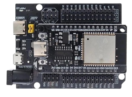
The ESP32 30pin Expansion Board is a versatile and user-friendly development board designed to extend the functionality of the ESP32 microcontroller. Manufactured by ESP, this board features 30 pins, providing easy connectivity to a wide range of sensors, modules, and peripherals. It is ideal for rapid prototyping, IoT applications, and embedded systems development.
Explore Projects Built with ESP32 30pin Expansion Board


Explore Projects Built with ESP32 30pin Expansion Board
Common Applications and Use Cases
- Internet of Things (IoT) devices and smart home systems
- Prototyping with sensors and actuators
- Wireless communication projects (Wi-Fi and Bluetooth)
- Robotics and automation systems
- Educational projects and learning platforms
Technical Specifications
The following table outlines the key technical details of the ESP32 30pin Expansion Board:
| Specification | Details |
|---|---|
| Manufacturer | ESP |
| Manufacturer Part ID | ESP32 |
| Microcontroller | ESP32 (dual-core, 32-bit processor) |
| Operating Voltage | 3.3V |
| Input Voltage Range | 5V (via USB) |
| GPIO Pins | 30 pins (including digital, analog, PWM, I2C, SPI, UART) |
| Communication Protocols | Wi-Fi (802.11 b/g/n), Bluetooth 4.2 (Classic and BLE) |
| Flash Memory | 4MB (varies by model) |
| Clock Speed | Up to 240 MHz |
| Dimensions | 57mm x 25mm x 13mm |
| USB Interface | Micro-USB for power and programming |
| Power Consumption | Low-power modes available (deep sleep current: ~10 µA) |
Pin Configuration and Descriptions
The ESP32 30pin Expansion Board features a 30-pin layout. Below is a table describing the pin configuration:
| Pin Number | Pin Name | Description |
|---|---|---|
| 1 | GND | Ground pin |
| 2 | 3V3 | 3.3V power output |
| 3 | EN | Enable pin (active high, used to reset the board) |
| 4 | IO1 | GPIO1 (UART TX) |
| 5 | IO3 | GPIO3 (UART RX) |
| 6 | IO4 | GPIO4 (PWM, ADC, or digital I/O) |
| 7 | IO5 | GPIO5 (PWM, ADC, or digital I/O) |
| 8 | IO12 | GPIO12 (PWM, ADC, or digital I/O) |
| 9 | IO13 | GPIO13 (PWM, ADC, or digital I/O) |
| 10 | IO14 | GPIO14 (PWM, ADC, or digital I/O) |
| 11 | IO15 | GPIO15 (PWM, ADC, or digital I/O) |
| 12 | IO16 | GPIO16 (PWM, ADC, or digital I/O) |
| 13 | IO17 | GPIO17 (PWM, ADC, or digital I/O) |
| 14 | IO18 | GPIO18 (SPI SCK, PWM, or digital I/O) |
| 15 | IO19 | GPIO19 (SPI MISO, PWM, or digital I/O) |
| 16 | IO21 | GPIO21 (I2C SDA, PWM, or digital I/O) |
| 17 | IO22 | GPIO22 (I2C SCL, PWM, or digital I/O) |
| 18 | IO23 | GPIO23 (SPI MOSI, PWM, or digital I/O) |
| 19 | IO25 | GPIO25 (PWM, ADC, or digital I/O) |
| 20 | IO26 | GPIO26 (PWM, ADC, or digital I/O) |
| 21 | IO27 | GPIO27 (PWM, ADC, or digital I/O) |
| 22 | IO32 | GPIO32 (PWM, ADC, or digital I/O) |
| 23 | IO33 | GPIO33 (PWM, ADC, or digital I/O) |
| 24 | IO34 | GPIO34 (ADC or digital input only) |
| 25 | IO35 | GPIO35 (ADC or digital input only) |
| 26 | VIN | Input voltage (5V from USB or external power source) |
| 27 | GND | Ground pin |
| 28 | IO36 | GPIO36 (ADC or digital input only) |
| 29 | IO39 | GPIO39 (ADC or digital input only) |
| 30 | RST | Reset pin (active low, used to reset the board) |
Usage Instructions
How to Use the Component in a Circuit
Powering the Board:
- Connect the board to a computer or USB power source using a Micro-USB cable.
- Alternatively, supply 5V to the VIN pin and GND pin for external power.
Programming the Board:
- Install the ESP32 board package in the Arduino IDE or use the ESP-IDF framework.
- Select the appropriate board (e.g., "ESP32 Dev Module") in the IDE.
- Connect the board to your computer via USB and upload your code.
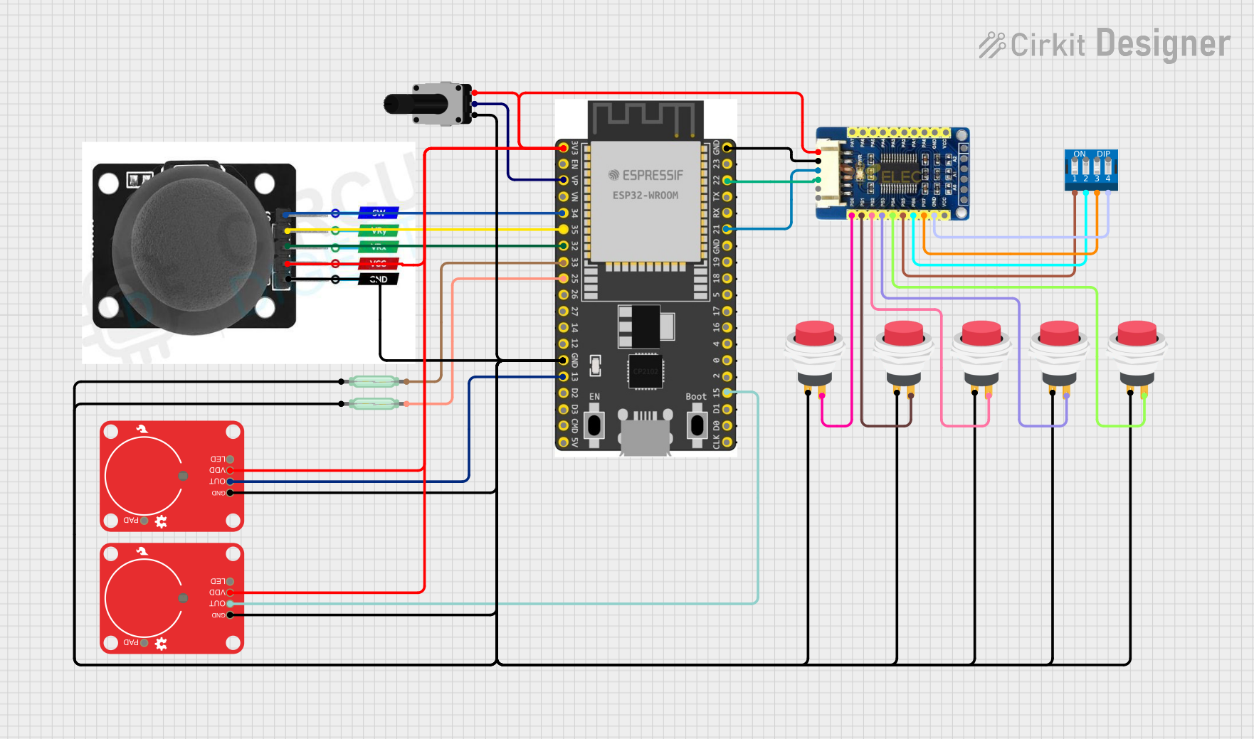
Connecting Peripherals:
- Use the GPIO pins to connect sensors, actuators, or other modules.
- Ensure that the voltage levels of connected devices are compatible with the 3.3V logic of the ESP32.
Communication Protocols:
- Use I2C, SPI, or UART pins to interface with external devices.
- Configure the pins in your code as needed for the specific protocol.
Important Considerations and Best Practices
- Voltage Levels: The GPIO pins operate at 3.3V. Avoid connecting 5V devices directly to the pins without a level shifter.
- Power Supply: Ensure a stable power supply to avoid unexpected resets or malfunctions.
- Pin Multiplexing: Some pins have multiple functions (e.g., ADC, PWM, I2C). Configure them carefully in your code to avoid conflicts.
- Deep Sleep Mode: Use deep sleep mode to reduce power consumption in battery-powered applications.
Example Code for Arduino UNO Integration
Below is an example of how to blink an LED connected to GPIO2 on the ESP32:
// Example: Blink an LED connected to GPIO2 on the ESP32

// Define the GPIO pin for the LED
const int ledPin = 2;

void setup() {
  // Initialize the LED pin as an output
  pinMode(ledPin, OUTPUT);
}

void loop() {
  // Turn the LED on
  digitalWrite(ledPin, HIGH);
  delay(1000); // Wait for 1 second

  // Turn the LED off
  digitalWrite(ledPin, LOW);
  delay(1000); // Wait for 1 second
}
Troubleshooting and FAQs
Common Issues and Solutions
The board is not detected by the computer:
- Ensure the USB cable is functional and supports data transfer.
- Install the correct USB-to-serial driver for the ESP32.
Upload errors in the Arduino IDE:
- Check that the correct board and COM port are selected in the IDE.
- Press and hold the "BOOT" button on the board while uploading the code.
Unstable operation or frequent resets:
- Verify that the power supply is stable and sufficient.
- Avoid using GPIO pins that are reserved for specific functions (e.g., GPIO0, GPIO2).
Wi-Fi or Bluetooth not working:
- Ensure the antenna is not obstructed.
- Check the Wi-Fi or Bluetooth configuration in your code.
FAQs
Q: Can I power the board with a battery?
A: Yes, you can use a 3.7V LiPo battery connected to the VIN and GND pins. Ensure the battery voltage is regulated.
Q: What is the maximum current output of the 3.3V pin?
A: The 3.3V pin can supply up to 500mA, depending on the input power source.
Q: Can I use the board with MicroPython?
A: Yes, the ESP32 supports MicroPython. Flash the MicroPython firmware to the board and use a compatible IDE like Thonny.
Q: Are all GPIO pins available for general use?
A: No, some GPIO pins have specific functions or limitations. Refer to the pin configuration table for details.