How to Use ESP32 38-PIN: Examples, Pinouts, and Specs
Introduction
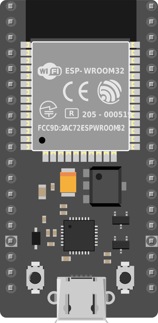
The ESP32 38-PIN is a powerful and versatile microcontroller designed for a wide range of applications, particularly in the Internet of Things (IoT) and embedded systems. It features built-in Wi-Fi and Bluetooth capabilities, making it an excellent choice for wireless communication projects. With 38 pins, the ESP32 offers extensive input/output (I/O) options, enabling developers to connect various sensors, actuators, and peripherals.
Explore Projects Built with ESP32 38-PIN


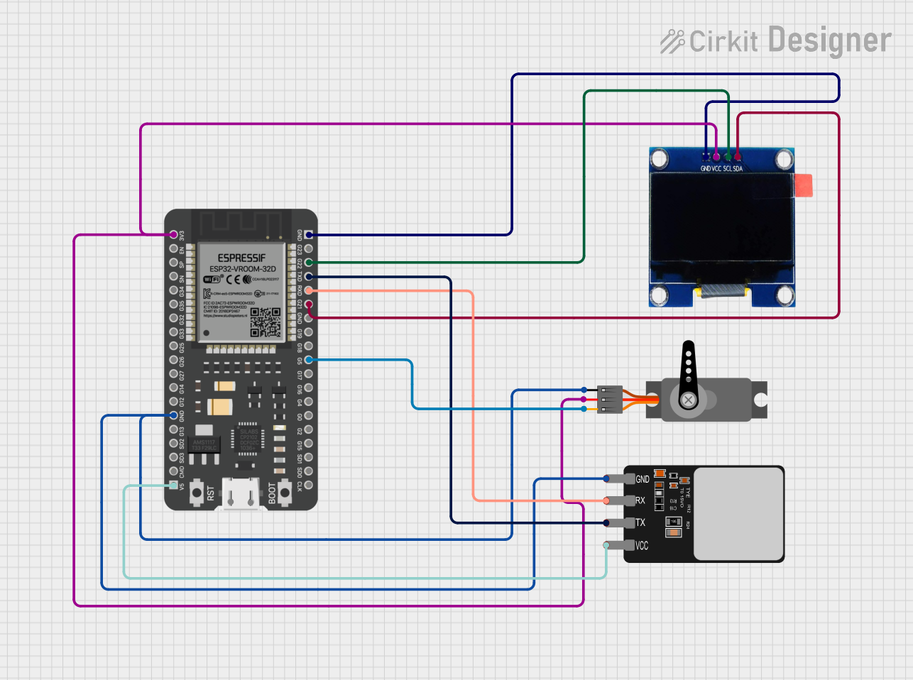
Explore Projects Built with ESP32 38-PIN
Common Applications and Use Cases
- IoT devices and smart home automation
- Wireless sensor networks
- Wearable technology
- Robotics and automation systems
- Data logging and remote monitoring
- Prototyping and educational projects
Technical Specifications
The ESP32 38-PIN microcontroller is equipped with robust hardware and connectivity features. Below are its key technical specifications:
| Specification | Details |
|---|---|
| Microcontroller | Tensilica Xtensa LX6 dual-core processor |
| Clock Speed | Up to 240 MHz |
| Flash Memory | 4 MB (varies by model) |
| SRAM | 520 KB |
| Wi-Fi | 802.11 b/g/n |
| Bluetooth | Bluetooth 4.2 and BLE (Bluetooth Low Energy) |
| Operating Voltage | 3.3V |
| Input Voltage Range | 5V (via USB) or 7-12V (via VIN pin) |
| GPIO Pins | 34 (multipurpose, including ADC, DAC, PWM, I2C, SPI, UART) |
| ADC Channels | 18 (12-bit resolution) |
| DAC Channels | 2 |
| PWM Channels | 16 |
| Communication Protocols | UART, SPI, I2C, I2S, CAN, Ethernet |
| Power Consumption | Ultra-low power consumption in deep sleep mode (as low as 10 µA) |
| Dimensions | 51mm x 25.5mm |
Pin Configuration and Descriptions
The ESP32 38-PIN has a total of 38 pins, each with specific functions. Below is a summary of the pin configuration:
| Pin Name | Function |
|---|---|
| VIN | Input power supply (7-12V) |
| GND | Ground |
| 3V3 | 3.3V output |
| EN | Enable pin (active high) |
| IO0 | GPIO0, used for boot mode selection |
| IO2 | GPIO2, general-purpose I/O |
| IO4 | GPIO4, general-purpose I/O |
| IO5 | GPIO5, general-purpose I/O |
| IO12 | GPIO12, general-purpose I/O |
| IO13 | GPIO13, general-purpose I/O |
| IO14 | GPIO14, general-purpose I/O |
| IO15 | GPIO15, general-purpose I/O |
| IO16 | GPIO16, general-purpose I/O |
| IO17 | GPIO17, general-purpose I/O |
| IO18 | GPIO18, general-purpose I/O |
| IO19 | GPIO19, general-purpose I/O |
| IO21 | GPIO21, general-purpose I/O |
| IO22 | GPIO22, general-purpose I/O |
| IO23 | GPIO23, general-purpose I/O |
| IO25 | GPIO25, general-purpose I/O |
| IO26 | GPIO26, general-purpose I/O |
| IO27 | GPIO27, general-purpose I/O |
| IO32 | GPIO32, general-purpose I/O |
| IO33 | GPIO33, general-purpose I/O |
| IO34 | GPIO34, input-only pin |
| IO35 | GPIO35, input-only pin |
| ADC1/ADC2 | Analog-to-digital converter channels |
| DAC1/DAC2 | Digital-to-analog converter channels |
| TX0/RX0 | UART0 TX/RX pins |
| TX1/RX1 | UART1 TX/RX pins |
| TX2/RX2 | UART2 TX/RX pins |
| SCL/SDA | I2C clock and data pins |
| MOSI/MISO | SPI data pins |
| SCK/CS | SPI clock and chip select pins |
Usage Instructions
How to Use the ESP32 38-PIN in a Circuit
Powering the ESP32:
- Use the VIN pin to supply 7-12V, or connect a 5V USB power source.
- Ensure the GND pin is connected to the ground of your circuit.
Programming the ESP32:
- Connect the ESP32 to your computer via a USB cable.
- Install the ESP32 board package in the Arduino IDE or use the ESP-IDF framework.
- Select the correct board and port in the IDE before uploading code.
Connecting Peripherals:
- Use GPIO pins for digital I/O, ADC pins for analog input, and DAC pins for analog output.
- For communication, use UART, SPI, or I2C pins as needed.
Wi-Fi and Bluetooth Setup:
- Use the built-in libraries (e.g.,
WiFi.handBluetoothSerial.hin Arduino IDE) to configure wireless communication.
- Use the built-in libraries (e.g.,
Important Considerations and Best Practices
- Always use a level shifter when interfacing 5V devices with the ESP32, as its GPIO pins operate at 3.3V.
- Avoid using GPIO pins 6-11, as they are reserved for the internal flash memory.
- Use decoupling capacitors near the power pins to reduce noise and ensure stable operation.
- When using Wi-Fi or Bluetooth, ensure proper antenna placement to avoid signal interference.
Example Code for Arduino UNO Integration
Below is an example of using the ESP32 to connect to a Wi-Fi network and send data to a server:
#include <WiFi.h> // Include the Wi-Fi library

const char* ssid = "Your_SSID";       // Replace with your Wi-Fi network name
const char* password = "Your_Password"; // Replace with your Wi-Fi password

void setup() {
  Serial.begin(115200); // Initialize serial communication at 115200 baud
  WiFi.begin(ssid, password); // Connect to the Wi-Fi network

  Serial.print("Connecting to Wi-Fi");
  while (WiFi.status() != WL_CONNECTED) {
    delay(500); // Wait for connection
    Serial.print(".");
  }
  Serial.println("\nConnected to Wi-Fi!");
  Serial.print("IP Address: ");
  Serial.println(WiFi.localIP()); // Print the ESP32's IP address
}

void loop() {
  // Add your main code here
}
Troubleshooting and FAQs
Common Issues and Solutions
ESP32 Not Connecting to Wi-Fi:
- Double-check the SSID and password.
- Ensure the router is within range and supports 2.4 GHz Wi-Fi (ESP32 does not support 5 GHz).
Upload Errors in Arduino IDE:
- Ensure the correct board and port are selected in the IDE.
- Press and hold the "BOOT" button on the ESP32 while uploading the code.
Random Resets or Instability:
- Check the power supply for sufficient current (at least 500 mA).
- Add decoupling capacitors to stabilize the power supply.
GPIO Pin Not Working:
- Verify the pin is not reserved for internal use (e.g., GPIO6-GPIO11).
- Check for proper pinMode configuration in the code.
FAQs
Can the ESP32 operate on battery power?
Yes, the ESP32 can be powered by a LiPo battery connected to the VIN pin. Use a voltage regulator if needed.How do I reset the ESP32?
Press the "EN" button on the board to reset the microcontroller.Can I use the ESP32 with 5V logic devices?
No, the ESP32 operates at 3.3V logic. Use a level shifter for compatibility with 5V devices.