How to Use Carte thermostat ACI 230V Kitable: Examples, Pinouts, and Specs
Introduction
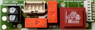
The Carte Thermostat ACI 230V Kitable is a 230V thermostat control board designed for managing heating and cooling systems. It provides precise temperature regulation and enhances energy efficiency, making it an ideal solution for residential, commercial, and industrial applications. This component is particularly useful in systems requiring automated temperature control, such as HVAC systems, water heaters, and refrigeration units.
Explore Projects Built with Carte thermostat ACI 230V Kitable


Explore Projects Built with Carte thermostat ACI 230V Kitable
Common Applications and Use Cases
- HVAC (Heating, Ventilation, and Air Conditioning) systems
- Water heaters and boilers
- Refrigeration and cooling systems
- Industrial temperature control systems
- Smart home automation for climate control
Technical Specifications
Key Technical Details
| Parameter | Value |
|---|---|
| Operating Voltage | 230V AC |
| Maximum Load Current | 10A |
| Temperature Range | -10°C to 110°C |
| Temperature Accuracy | ±1°C |
| Control Output | Relay (NO/NC) |
| Power Consumption | < 2W |
| Dimensions | 85mm x 55mm x 30mm |
| Mounting Type | PCB Mount or Enclosure Ready |
Pin Configuration and Descriptions
| Pin Number | Label | Description |
|---|---|---|
| 1 | L (Line) | Connect to the live wire of the 230V AC power supply. |
| 2 | N (Neutral) | Connect to the neutral wire of the 230V AC power supply. |
| 3 | NO (Relay) | Normally Open relay output for controlling the load (e.g., heater or fan). |
| 4 | NC (Relay) | Normally Closed relay output for controlling the load. |
| 5 | COM (Relay) | Common terminal for the relay output. |
| 6 | TEMP+ | Positive terminal for the external temperature sensor. |
| 7 | TEMP- | Negative terminal for the external temperature sensor. |
Usage Instructions
How to Use the Component in a Circuit
- Power Connection: Connect the
LandNpins to the 230V AC power supply. Ensure proper insulation and safety precautions when working with high voltage. - Load Connection: Connect the load (e.g., heater, fan, or cooling device) to the relay output terminals (
NO,NC, andCOM) based on the desired control logic:- Use
NOandCOMfor devices that should turn on when the relay is activated. - Use
NCandCOMfor devices that should turn off when the relay is activated.
- Use
- Temperature Sensor: Attach the external temperature sensor to the
TEMP+andTEMP-terminals. Place the sensor in the desired location for accurate temperature measurement. - Configuration: Adjust the thermostat settings (e.g., target temperature) using the onboard controls or external interface, if available.
- Testing: Power on the system and verify that the relay activates and deactivates based on the temperature readings and setpoints.
Important Considerations and Best Practices
- Safety First: Always disconnect the power supply before wiring or modifying the circuit. Use proper insulation and grounding to prevent electrical hazards.
- Sensor Placement: Position the temperature sensor away from heat sources or airflow obstructions to ensure accurate readings.
- Load Ratings: Ensure the connected load does not exceed the relay's maximum current rating (10A). Use an external relay or contactor for higher loads.
- Ventilation: Install the board in a well-ventilated enclosure to prevent overheating.
- Testing: Test the system with a low-power load before connecting high-power devices.
Arduino UNO Integration Example
The Carte Thermostat ACI 230V Kitable can be integrated with an Arduino UNO for advanced control and monitoring. Below is an example code snippet for reading the temperature sensor and controlling the relay:
// Define pin connections
const int relayPin = 7; // Connect to the relay control pin
const int tempSensorPin = A0; // Connect to the temperature sensor output

// Define temperature thresholds
const float tempThresholdHigh = 30.0; // High temperature threshold in °C
const float tempThresholdLow = 25.0;  // Low temperature threshold in °C

void setup() {
  pinMode(relayPin, OUTPUT); // Set relay pin as output
  digitalWrite(relayPin, LOW); // Ensure relay is off initially
  Serial.begin(9600); // Initialize serial communication for debugging
}

void loop() {
  // Read the temperature sensor value (example: analog input)
  int sensorValue = analogRead(tempSensorPin);

  // Convert sensor value to temperature (example conversion)
  float temperature = (sensorValue / 1023.0) * 100.0; // Adjust based on sensor specs

  // Print temperature to serial monitor
  Serial.print("Temperature: ");
  Serial.print(temperature);
  Serial.println(" °C");

  // Control relay based on temperature thresholds
  if (temperature > tempThresholdHigh) {
    digitalWrite(relayPin, HIGH); // Turn on relay (e.g., activate cooling)
  } else if (temperature < tempThresholdLow) {
    digitalWrite(relayPin, LOW); // Turn off relay (e.g., deactivate cooling)
  }

  delay(1000); // Wait 1 second before next reading
}
Troubleshooting and FAQs
Common Issues and Solutions
Relay Not Activating:
- Cause: Incorrect wiring or insufficient power supply.
- Solution: Verify the wiring connections and ensure the power supply meets the board's requirements.
Inaccurate Temperature Readings:
- Cause: Poor sensor placement or faulty sensor.
- Solution: Reposition the sensor for better accuracy or replace it if damaged.
Overheating of the Board:
- Cause: High ambient temperature or excessive load.
- Solution: Improve ventilation or reduce the load on the relay.
Load Not Responding:
- Cause: Incorrect relay wiring or load exceeding the relay's capacity.
- Solution: Double-check the relay connections and ensure the load is within the specified limits.
FAQs
Can I use this board with a DC power supply? No, the board is designed for 230V AC operation only.
What type of temperature sensor is compatible? The board typically supports NTC thermistors or similar sensors. Refer to the manufacturer's specifications for compatibility.
Can I control multiple devices with this board? Yes, but ensure the total load does not exceed the relay's maximum current rating. Use external relays for additional devices if needed.
Is this board suitable for outdoor use? The board is not weatherproof. Use a suitable enclosure for outdoor installations.