How to Use IR Transmitter: Examples, Pinouts, and Specs
Introduction
An infrared (IR) transmitter is an electronic device that emits infrared radiation to transmit signals wirelessly. This form of invisible light is commonly used in remote control systems for televisions, air conditioners, and other consumer electronics. IR transmitters are also used in object detection systems, communication devices, and various types of automation.
Explore Projects Built with IR Transmitter
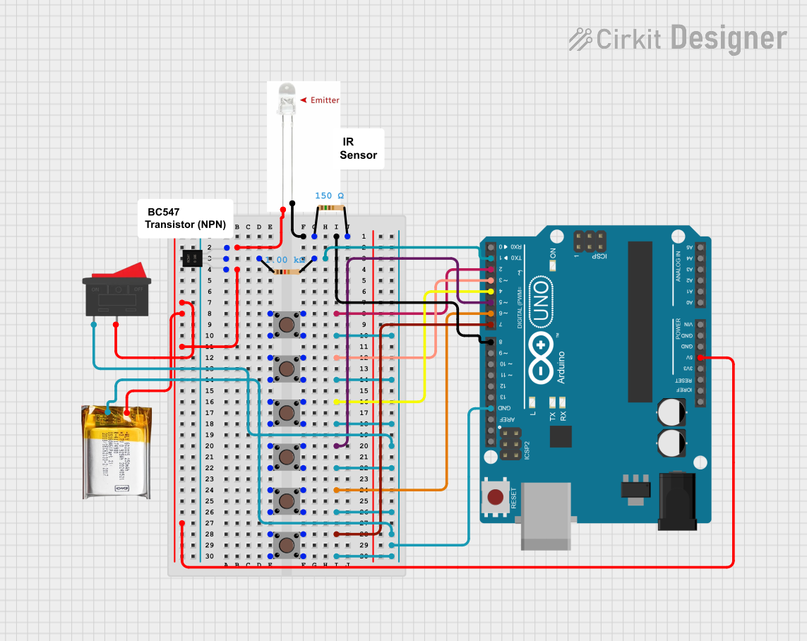
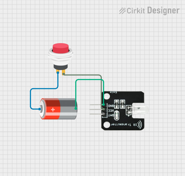
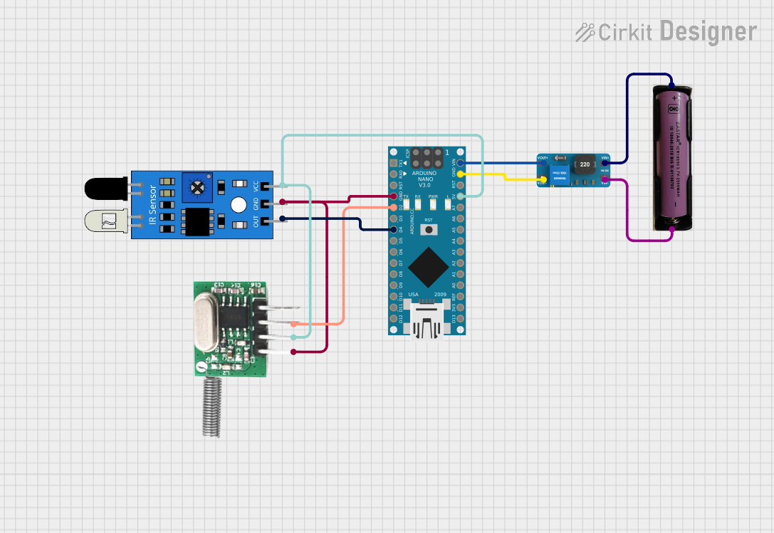

Explore Projects Built with IR Transmitter
Common Applications and Use Cases
- Remote controls for TVs, DVD players, and other home entertainment systems
- Wireless communication between devices
- Object detection and proximity sensors
- Home automation systems
- Infrared beacons for localization
Technical Specifications
Key Technical Details
- Wavelength: Typically ranges from 850 nm to 950 nm
- Operating Voltage: Usually between 3V to 5V
- Forward Current (If): 20 mA to 100 mA (check datasheet for exact value)
- Radiant Power: Depends on the model, often in the range of 10 mW to 100 mW
- Viewing Angle: Varies by model, common angles include 20°, 30°, 45°
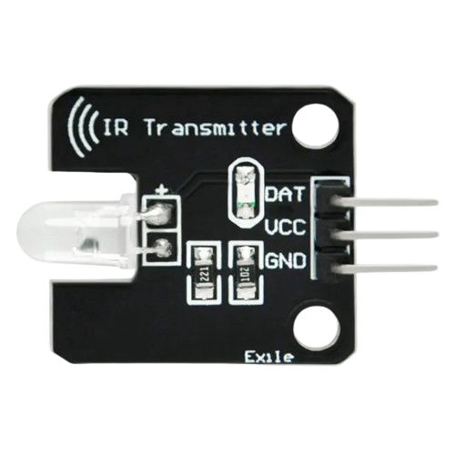
Pin Configuration and Descriptions
| Pin Number | Name | Description |
|---|---|---|
| 1 | Anode (+) | Connects to the positive supply voltage |
| 2 | Cathode (-) | Connects to the ground (0V) |
Usage Instructions
How to Use the Component in a Circuit
Power Supply: Connect the anode of the IR transmitter to a suitable power supply (3V to 5V), ensuring that the current does not exceed the specified forward current.
Current Limiting Resistor: Place a current-limiting resistor in series with the anode to prevent damage to the IR LED. Calculate the resistor value using Ohm's law:
R = (V_supply - V_forward) / I_forward.Signal Input: To modulate the IR signal, connect the anode to a microcontroller or oscillator circuit capable of generating the desired signal pattern.
Ground Connection: Connect the cathode of the IR transmitter to the ground of the power supply.
Important Considerations and Best Practices
- Modulation: To avoid interference from ambient light, the IR signal is often modulated at a specific frequency (e.g., 38 kHz).
- Line of Sight: IR communication requires a clear line of sight between the transmitter and receiver.
- Distance and Angle: Be aware of the effective range and viewing angle of the IR transmitter for reliable signal transmission.
- Heat Dissipation: Ensure proper heat sinking if operating the IR transmitter at high power levels.
Example Arduino Code
#include <IRremote.h>

IRsend irsend;

void setup() {
  // Start the serial communication
  Serial.begin(9600);
}

void loop() {
  // Example: Send an IR signal (NEC encoded) every 5 seconds
  if (Serial.available() > 0) {
    int input = Serial.parseInt(); // Read the input as an integer
    irsend.sendNEC(input, 32); // Send the NEC encoded input
    Serial.println("Signal sent");
    delay(5000); // Wait for 5 seconds before sending the next signal
  }
}
Troubleshooting and FAQs
Common Issues Users Might Face
- No Signal: Ensure the IR transmitter is properly connected with correct polarity and that the power supply is within the specified range.
- Weak Signal: Check if the current-limiting resistor is too high, reducing the IR LED's intensity. Also, verify that the IR LED is not damaged.
- Interference: If the IR receiver is not responding correctly, ensure there is no ambient light interference and that the signal is modulated at the correct frequency.
Solutions and Tips for Troubleshooting
- Check Connections: Verify all connections are secure and correct.
- Test with a Camera: Use a digital camera or smartphone camera to see if the IR transmitter is emitting light when activated.
- Signal Modulation: Ensure that the signal is being modulated at the correct frequency for the receiver.
- Replace the Component: If all else fails, the IR transmitter may be faulty and need replacement.
Remember to always refer to the specific datasheet of the IR transmitter model you are using for precise information on operating conditions and limitations.