How to Use DC MCB: Examples, Pinouts, and Specs
Introduction
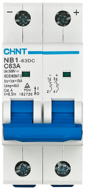
The DC MCB (Miniature Circuit Breaker), model NB1-63DC, manufactured by CHINT, is a protective device specifically designed for direct current (DC) applications. It automatically disconnects a circuit in the event of an overload or short circuit, ensuring the safety of electrical systems and preventing potential damage to connected equipment. This component is widely used in renewable energy systems, battery banks, electric vehicles, and industrial DC circuits.
Explore Projects Built with DC MCB

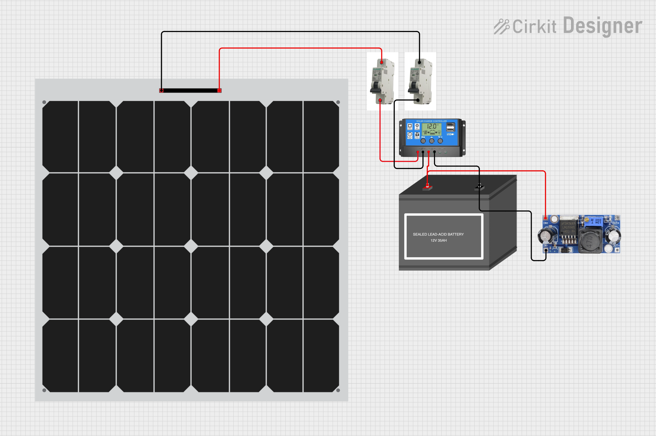

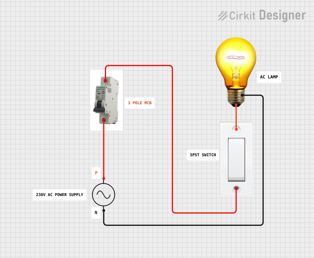
Explore Projects Built with DC MCB
Common Applications and Use Cases
- Solar Power Systems: Protects photovoltaic (PV) arrays and DC distribution circuits.
- Battery Storage Systems: Ensures safe operation of battery banks by preventing overcurrent conditions.
- Electric Vehicles (EVs): Safeguards DC circuits in EV charging stations and onboard systems.
- Industrial DC Applications: Provides protection for DC motors, control panels, and other equipment.
- Telecommunication Systems: Secures DC power supplies in telecom infrastructure.
Technical Specifications
The following table outlines the key technical details of the NB1-63DC:
| Parameter | Specification |
|---|---|
| Rated Voltage (Ue) | 250V DC (1-pole), 500V DC (2-pole) |
| Rated Current (In) | 1A to 63A |
| Breaking Capacity (Icu) | 10kA |
| Number of Poles | 1P, 2P |
| Tripping Curve | C and D |
| Operating Temperature | -30°C to +70°C |
| Mounting | DIN Rail (35mm) |
| Standards Compliance | IEC/EN 60947-2, GB/T 14048.2 |
Pin Configuration and Descriptions
The NB1-63DC does not have traditional pins but features terminal connections for input and output. The table below describes the terminal configuration:
| Terminal | Description |
|---|---|
| Line (L) | Connects to the positive DC input (power source). |
| Load (OUT) | Connects to the positive DC output (load side). |
| Neutral (N) | Optional, used in some configurations. |
Usage Instructions
How to Use the Component in a Circuit
- Determine the Current Rating: Select the appropriate current rating (1A to 63A) based on the load requirements of your DC circuit.
- Mounting: Secure the MCB onto a standard 35mm DIN rail in your distribution box or panel.
- Wiring:
- Connect the Line (L) terminal to the positive terminal of the DC power source.
- Connect the Load (OUT) terminal to the positive terminal of the load.
- If applicable, connect the Neutral (N) terminal to the negative side of the circuit.
- Power On: Once all connections are secure, switch on the MCB to energize the circuit.
- Testing: Test the circuit by simulating an overload or short circuit to ensure the MCB trips as expected.
Important Considerations and Best Practices
- Polarity: Ensure correct polarity when connecting the MCB to avoid malfunction.
- Voltage Rating: Do not exceed the rated voltage of 250V DC (1-pole) or 500V DC (2-pole).
- Current Rating: Select an MCB with a current rating slightly higher than the normal operating current of your circuit but below the maximum current capacity of the wiring.
- Environmental Conditions: Install the MCB in a dry, dust-free environment within the specified operating temperature range (-30°C to +70°C).
- Periodic Inspection: Regularly inspect the MCB for signs of wear, damage, or loose connections.
Arduino Integration
While DC MCBs are not directly interfaced with microcontrollers like Arduino, they can be used in circuits powered by DC sources controlled by Arduino. For example, an Arduino can monitor the current in a DC circuit using a current sensor and trigger an alert if the MCB trips.
/*
  Example Arduino Code to Monitor DC Circuit Current
  This code uses a current sensor (e.g., ACS712) to monitor the current
  in a DC circuit protected by an MCB. If the current exceeds a threshold,
  the Arduino triggers an alert.
*/

const int currentSensorPin = A0; // Analog pin connected to the current sensor
const float currentThreshold = 10.0; // Current threshold in amps

void setup() {
  Serial.begin(9600); // Initialize serial communication
  pinMode(currentSensorPin, INPUT); // Set the sensor pin as input
}

void loop() {
  int sensorValue = analogRead(currentSensorPin); // Read sensor value
  float current = (sensorValue / 1023.0) * 30.0; // Convert to current (example for ACS712)

  Serial.print("Current: ");
  Serial.print(current);
  Serial.println(" A");

  if (current > currentThreshold) {
    Serial.println("Warning: Current exceeds threshold! Check MCB.");
  }

  delay(1000); // Delay for 1 second
}
Troubleshooting and FAQs
Common Issues Users Might Face
MCB Does Not Trip During Overload:
- Cause: Incorrect current rating or faulty MCB.
- Solution: Verify the current rating and replace the MCB if necessary.
MCB Trips Frequently:
- Cause: Overloaded circuit or short circuit.
- Solution: Reduce the load or inspect the circuit for faults.
Loose Connections:
- Cause: Improperly tightened terminals.
- Solution: Ensure all terminal screws are securely tightened.
MCB Does Not Reset:
- Cause: Persistent fault in the circuit.
- Solution: Identify and resolve the fault before attempting to reset the MCB.
Solutions and Tips for Troubleshooting
- Use a multimeter to check for short circuits or excessive current draw in the circuit.
- Ensure the MCB is installed in the correct orientation and polarity.
- Regularly inspect the MCB for signs of wear, such as discoloration or damaged terminals.
- If the MCB trips repeatedly, consider upgrading to a higher-rated model, provided it is within the safe limits of your circuit.
By following this documentation, users can effectively integrate and maintain the CHINT NB1-63DC in their DC electrical systems, ensuring reliable protection and optimal performance.