How to Use Lora llcc68: Examples, Pinouts, and Specs
Introduction
The Lora LLCC68 is a low-power, long-range transceiver module designed for Internet of Things (IoT) applications. It operates on the LoRaWAN protocol, which enables wireless communication over distances of several kilometers while maintaining minimal power consumption. This makes the LLCC68 an excellent choice for battery-operated devices and applications requiring reliable, long-range communication.
Explore Projects Built with Lora llcc68


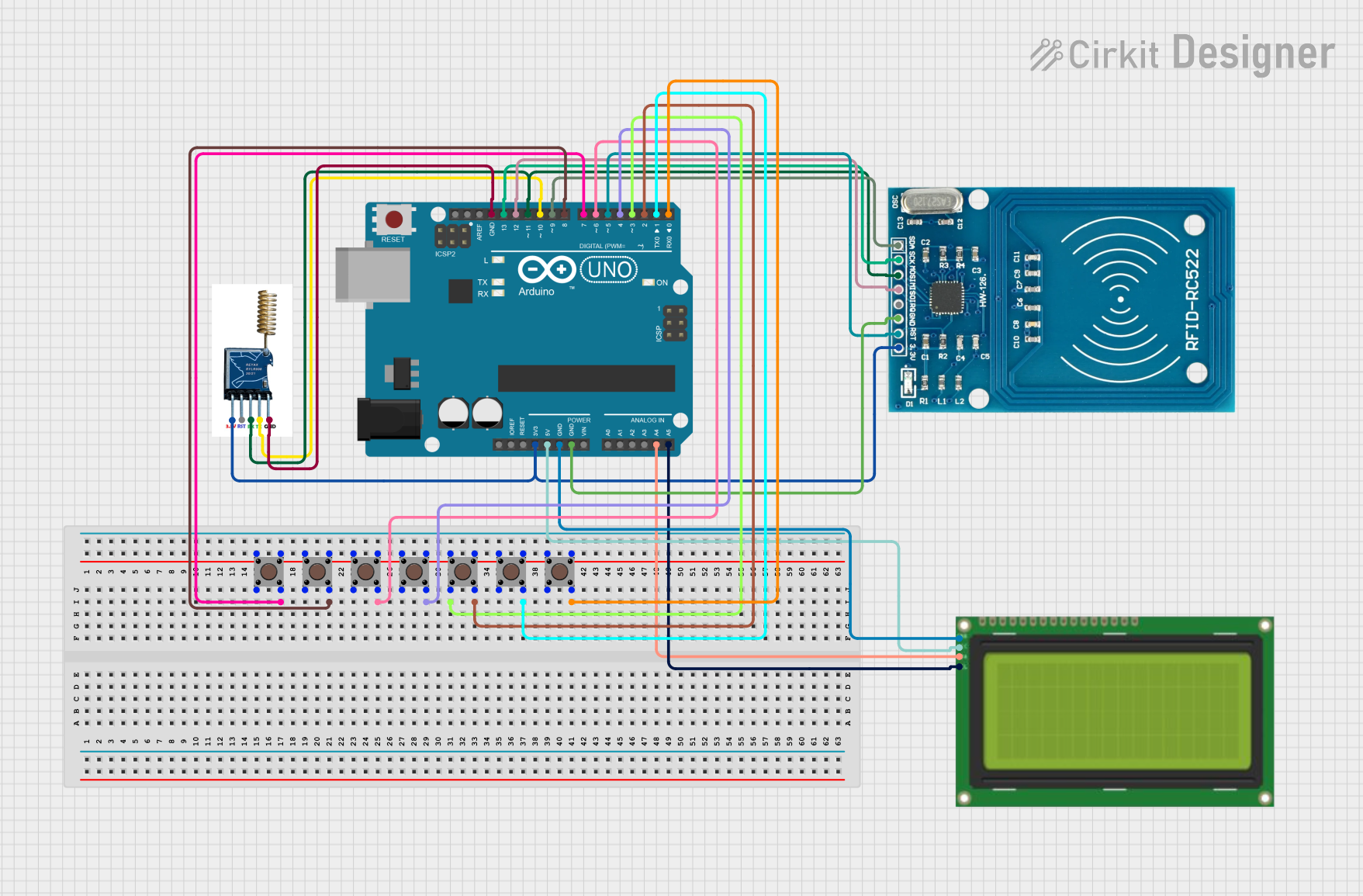
Explore Projects Built with Lora llcc68
Common Applications and Use Cases
- Smart agriculture (e.g., soil moisture monitoring, weather stations)
- Industrial automation and monitoring
- Smart cities (e.g., parking sensors, waste management)
- Asset tracking and geolocation
- Environmental monitoring (e.g., air quality sensors)
- Home automation and security systems
Technical Specifications
Key Technical Details
| Parameter | Value |
|---|---|
| Operating Frequency | 150 MHz to 960 MHz |
| Modulation | LoRa, FSK, GFSK |
| Output Power | Up to +22 dBm |
| Sensitivity | Down to -129 dBm (LoRa mode) |
| Supply Voltage | 1.8V to 3.7V |
| Current Consumption | 4.2 mA (receive mode), 22 mA (transmit) |
| Data Rate | 0.018 kbps to 62.5 kbps (LoRa mode) |
| Communication Range | Up to 15 km (line of sight) |
| Operating Temperature | -40°C to +85°C |
| Package Type | QFN-24 |
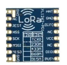
Pin Configuration and Descriptions
The Lora LLCC68 module typically comes in a QFN-24 package. Below is the pin configuration:
| Pin Number | Pin Name | Description |
|---|---|---|
| 1 | GND | Ground |
| 2 | VDD | Power supply input (1.8V to 3.7V) |
| 3 | RESET | Reset pin (active low) |
| 4 | DIO1 | Digital I/O 1 (interrupt or status pin) |
| 5 | DIO2 | Digital I/O 2 (optional functionality) |
| 6 | DIO3 | Digital I/O 3 (optional functionality) |
| 7 | TX/RX | RF switch control (transmit/receive) |
| 8 | ANT | Antenna connection |
| 9 | SCK | SPI clock input |
| 10 | MISO | SPI data output |
| 11 | MOSI | SPI data input |
| 12 | NSS | SPI chip select (active low) |
| 13-24 | NC | Not connected |
Usage Instructions
How to Use the Component in a Circuit
- Power Supply: Connect the VDD pin to a regulated power source (1.8V to 3.7V) and GND to the ground of your circuit.
- Antenna: Attach a suitable antenna to the ANT pin for optimal signal transmission and reception.
- SPI Communication: Connect the SPI pins (SCK, MISO, MOSI, NSS) to the corresponding pins on your microcontroller for communication.
- Reset: Use the RESET pin to initialize the module when required.
- Digital I/O: Use DIO1, DIO2, and DIO3 for interrupts or other status signals as per your application.
Important Considerations and Best Practices
- Antenna Matching: Ensure proper impedance matching for the antenna to maximize range and minimize power loss.
- Power Supply: Use a low-noise, stable power supply to avoid interference with the RF signal.
- PCB Layout: Follow RF design best practices, such as keeping the antenna trace short and avoiding ground plane interruptions.
- Firmware: Use a compatible LoRaWAN stack or library to simplify communication with the module.
Example Code for Arduino UNO
Below is an example of how to interface the Lora LLCC68 with an Arduino UNO using the SPI interface:
#include <SPI.h>

// Define SPI pins for Arduino UNO
#define NSS 10  // Chip select pin
#define RESET 9 // Reset pin
#define DIO1 2  // Interrupt pin

void setup() {
  // Initialize serial communication for debugging
  Serial.begin(9600);

  // Initialize SPI communication
  SPI.begin();

  // Configure pins
  pinMode(NSS, OUTPUT);
  pinMode(RESET, OUTPUT);
  pinMode(DIO1, INPUT);

  // Reset the module
  digitalWrite(RESET, LOW);
  delay(10); // Hold reset low for 10ms
  digitalWrite(RESET, HIGH);
  delay(100); // Wait for the module to initialize

  Serial.println("Lora LLCC68 initialized.");
}

void loop() {
  // Example: Send a command to the module
  digitalWrite(NSS, LOW); // Select the module
  SPI.transfer(0x01);     // Example command (replace with actual command)
  digitalWrite(NSS, HIGH); // Deselect the module

  delay(1000); // Wait for 1 second
}
Notes:
- Replace the
SPI.transfer(0x01)line with actual commands based on your application. - Use a LoRaWAN library (e.g., LMIC or RadioLib) for more advanced functionality.
Troubleshooting and FAQs
Common Issues and Solutions
No Communication with the Module:
- Ensure the SPI connections are correct and match the microcontroller's SPI pins.
- Verify that the NSS pin is toggled correctly during communication.
Poor Signal Range:
- Check the antenna connection and ensure proper impedance matching.
- Avoid placing the module near sources of RF interference.
Module Not Responding After Reset:
- Ensure the RESET pin is held low for at least 10ms and then released.
- Verify the power supply voltage is within the specified range.
High Power Consumption:
- Ensure the module is in sleep mode when not actively transmitting or receiving.
- Check for any unnecessary operations in your firmware.
FAQs
Q: Can the Lora LLCC68 operate without a microcontroller?
A: No, the LLCC68 requires a microcontroller to configure and control its operation via SPI.
Q: What is the maximum range of the LLCC68?
A: The module can achieve a range of up to 15 km in line-of-sight conditions, depending on the environment and antenna quality.
Q: Is the LLCC68 compatible with LoRaWAN networks?
A: Yes, the LLCC68 is designed to operate with the LoRaWAN protocol for long-range communication.
Q: Can I use the LLCC68 for point-to-point communication?
A: Yes, the module supports point-to-point communication in addition to LoRaWAN.
Q: What libraries are recommended for Arduino?
A: Popular libraries include LMIC and RadioLib, which provide high-level APIs for LoRa communication.
By following this documentation, you can effectively integrate the Lora LLCC68 into your IoT projects and take advantage of its long-range, low-power capabilities.