
How to Use Sony's Spresense Main Board: Examples, Pinouts, and Specs
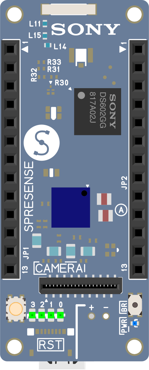
 Design with Sony's Spresense Main Board in Cirkit Designer
Introduction
Sony's Spresense Main Board (Part ID: CXD5602PWDMAIN1) is a compact and powerful microcontroller board designed for IoT (Internet of Things) applications. It features a multi-core processor, low power consumption, and extensive support for various sensors and connectivity options. This board is ideal for developers looking to create advanced IoT solutions, including smart devices, environmental monitoring systems, and audio processing applications.
Explore Projects Built with Sony's Spresense Main Board
 Open Project in Cirkit Designer
 Open Project in Cirkit Designer
 Open Project in Cirkit Designer
 Open Project in Cirkit Designer
Explore Projects Built with Sony's Spresense Main Board
Open Project in Cirkit DesignerOpen Project in Cirkit DesignerOpen Project in Cirkit DesignerOpen Project in Cirkit DesignerCommon Applications and Use Cases
- IoT devices and smart home systems
- Environmental monitoring and data logging
- GPS-based applications (e.g., tracking systems)
- Audio processing and voice recognition
- Edge AI and machine learning applications
- Prototyping for industrial automation
Technical Specifications
The Spresense Main Board is equipped with advanced hardware capabilities to support a wide range of applications. Below are the key technical details:
Key Technical Details
| Specification | Value |
|---|---|
| Processor | Sony CXD5602, ARM® Cortex®-M4F multi-core |
| Clock Speed | Up to 156 MHz |
| RAM | 1.5 MB |
| Flash Memory | 8 MB |
| Power Supply Voltage | 3.6V to 5.5V |
| Operating Temperature Range | -40°C to +85°C |
| Connectivity | UART, SPI, I2C, GPIO, PWM, ADC |
| GPS Support | Built-in GNSS receiver |
| Audio Support | High-resolution audio codec |
| Dimensions | 50 mm x 20.6 mm |
Pin Configuration and Descriptions
The Spresense Main Board features a 40-pin connector for interfacing with peripherals. Below is the pin configuration:
| Pin Number | Pin Name | Function | Description |
|---|---|---|---|
| 1 | VDD | Power Supply | Main power input (3.6V to 5.5V) |
| 2 | GND | Ground | Ground connection |
| 3 | GPIO0 | General Purpose I/O | Configurable digital I/O |
| 4 | GPIO1 | General Purpose I/O | Configurable digital I/O |
| 5 | UART_TX | UART Transmit | Serial communication TX |
| 6 | UART_RX | UART Receive | Serial communication RX |
| 7 | SPI_MOSI | SPI Master Out Slave In | SPI data output |
| 8 | SPI_MISO | SPI Master In Slave Out | SPI data input |
| 9 | SPI_SCK | SPI Clock | SPI clock signal |
| 10 | I2C_SCL | I2C Clock | I2C clock signal |
| 11 | I2C_SDA | I2C Data | I2C data signal |
| 12 | ADC0 | Analog Input | Analog-to-digital converter input |
| 13 | PWM0 | Pulse Width Modulation | PWM output |
| ... | ... | ... | ... |
For the full pinout, refer to the official Spresense documentation.
Usage Instructions
How to Use the Component in a Circuit
- Power Supply: Connect the VDD pin to a stable power source (3.6V to 5.5V) and the GND pin to ground.
- Peripheral Connections: Use the GPIO, UART, SPI, I2C, and ADC pins to interface with sensors, actuators, and other peripherals.
- Programming: The Spresense Main Board can be programmed using the Arduino IDE or the Spresense SDK. Install the necessary libraries and drivers before programming.
- Audio and GPS: For audio applications, connect a compatible microphone or speaker to the audio pins. For GPS applications, ensure the board has a clear view of the sky for optimal satellite reception.
Important Considerations and Best Practices
- Power Supply: Ensure the power supply voltage is within the specified range to avoid damaging the board.
- Heat Management: Operate the board within the recommended temperature range (-40°C to +85°C).
- Firmware Updates: Regularly update the firmware to access the latest features and bug fixes.
- Debugging: Use the UART pins for debugging and monitoring serial output.
Example Code for Arduino UNO Integration
Below is an example of how to use the Spresense Main Board with an Arduino UNO to read data from a sensor via I2C:
#include <Wire.h> // Include the Wire library for I2C communication

#define SENSOR_ADDRESS 0x68 // Replace with your sensor's I2C address

void setup() {
  Wire.begin(); // Initialize I2C communication
  Serial.begin(9600); // Start serial communication for debugging
  Serial.println("Spresense Main Board I2C Example");
}

void loop() {
  Wire.beginTransmission(SENSOR_ADDRESS); // Start communication with the sensor
  Wire.write(0x00); // Request data from the sensor (register 0x00)
  Wire.endTransmission();

  Wire.requestFrom(SENSOR_ADDRESS, 2); // Request 2 bytes of data
  if (Wire.available() == 2) {
    int data = Wire.read() << 8 | Wire.read(); // Combine the two bytes
    Serial.print("Sensor Data: ");
    Serial.println(data); // Print the sensor data
  } else {
    Serial.println("No data received from sensor");
  }

  delay(1000); // Wait for 1 second before the next reading
}
Troubleshooting and FAQs
Common Issues Users Might Face
Board Not Powering On:
- Ensure the power supply voltage is within the specified range (3.6V to 5.5V).
- Check the connections to the VDD and GND pins.
No Serial Output:
- Verify that the UART pins are correctly connected to the serial monitor.
- Ensure the correct baud rate is set in the serial monitor.
I2C Communication Fails:
- Check the I2C address of the connected device.
- Ensure proper pull-up resistors are used on the I2C lines.
GPS Not Working:
- Ensure the board has a clear view of the sky for satellite reception.
- Verify that the GPS module is enabled in the firmware.
Solutions and Tips for Troubleshooting
- Debugging: Use the serial monitor to print debug messages and identify issues.
- Documentation: Refer to the official Spresense documentation for detailed guidance.
- Community Support: Join the Spresense developer community for additional help and resources.
By following this documentation, users can effectively utilize Sony's Spresense Main Board for a wide range of IoT and embedded applications.