How to Use RAIN SENSOR: Examples, Pinouts, and Specs
Introduction
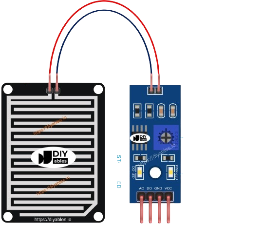
A rain sensor module is an electronic device that detects rainwater presence. It is commonly used in weather monitoring systems, automatic irrigation systems, and for home automation to control devices like rain gauges or windshield wipers. The sensor typically consists of a set of exposed traces on a circuit board. When water droplets fall onto the sensor, they bridge the traces and allow current to flow, which can be detected and measured.
Explore Projects Built with RAIN SENSOR
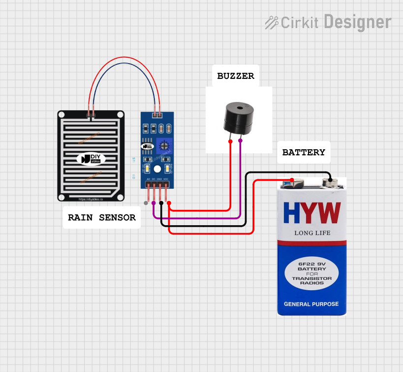
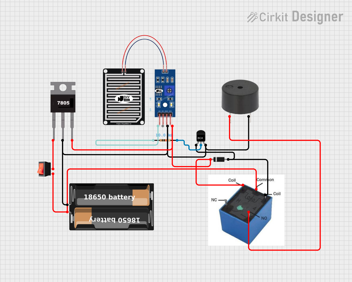
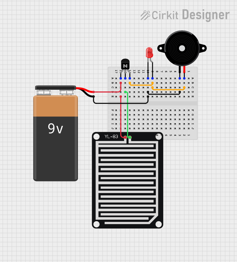
Explore Projects Built with RAIN SENSOR
Common Applications and Use Cases
- Automated irrigation systems
- Weather monitoring stations
- Automotive rain-sensing wiper controls
- Home automation systems for rain detection
- Outdoor event protection systems
Technical Specifications
Key Technical Details
- Operating Voltage: Typically 3.3V to 5V
- Output Type: Analog (varying voltage) and Digital (high/low signal)
- Sensitivity: Adjustable via onboard potentiometer
Pin Configuration and Descriptions
| Pin | Description |
|---|---|
| VCC | Connect to 3.3V or 5V power supply |
| GND | Connect to ground |
| DO | Digital output; goes high or low depending on rain detection |
| AO | Analog output; provides a variable voltage depending on the amount of water detected |
Usage Instructions
How to Use the Rain Sensor in a Circuit
- Connect the VCC pin to a 3.3V or 5V power supply.
- Connect the GND pin to the ground of the power supply.
- Connect the DO pin to a digital input pin on a microcontroller if you wish to use the digital output.
- Connect the AO pin to an analog input pin on a microcontroller if you wish to use the analog output.
- Adjust the onboard potentiometer to set the sensitivity of the digital output.
Important Considerations and Best Practices
- Ensure the sensor is mounted in a location where it can accurately collect rainwater.
- Avoid submerging the sensor to prevent damage.
- Use a pull-up or pull-down resistor with the digital output if required by your microcontroller.
- Calibrate the sensor by adjusting the potentiometer while simulating rain conditions.
- Protect the sensor's electronic components from water damage with appropriate housing.
Example Code for Arduino UNO
// Define the Arduino pin connected to the digital output of the rain sensor
const int rainSensorPin = 2;

void setup() {
  pinMode(rainSensorPin, INPUT);
  Serial.begin(9600);
}

void loop() {
  // Read the digital output from the rain sensor
  int sensorState = digitalRead(rainSensorPin);

  // Check if the sensor is detecting rain
  if (sensorState == HIGH) {
    Serial.println("It is raining!");
  } else {
    Serial.println("It is not raining.");
  }

  // Wait for a bit before reading again
  delay(500);
}
Troubleshooting and FAQs
Common Issues Users Might Face
- Sensor not responding: Ensure all connections are secure and the power supply is within the specified range.
- False readings: Adjust the sensitivity potentiometer, and make sure the sensor is not exposed to conductive materials or debris.
- Inconsistent output: Check for water damage or corrosion on the sensor's traces and clean them if necessary.
Solutions and Tips for Troubleshooting
- If the sensor gives constant high or low readings, recalibrate the sensitivity using the onboard potentiometer.
- Ensure the sensor is mounted in a way that water can easily reach the sensing area but does not pool on the sensor.
- Protect the sensor's circuitry from the elements with a weatherproof enclosure, but ensure the sensing area is exposed.
FAQs
Q: Can the rain sensor be used with a 3.3V system? A: Yes, the rain sensor can typically operate at 3.3V or 5V.
Q: How can I test the sensor without actual rain? A: You can simulate rain by dropping water onto the sensor's surface with a pipette or a spray bottle.
Q: Is it possible to use both the analog and digital outputs simultaneously? A: Yes, you can use both outputs at the same time to get both threshold-based (digital) and variable (analog) readings.
Q: How do I protect the sensor from water damage? A: Use a waterproof enclosure for the electronic components, leaving only the sensing area exposed.
This documentation provides a comprehensive guide to using a rain sensor module with an Arduino UNO or similar microcontroller. By following the instructions and best practices outlined above, users can effectively integrate this sensor into their projects for reliable rain detection.