
How to Use ESP32-WROOM-32UE: Examples, Pinouts, and Specs
 Design with ESP32-WROOM-32UE in Cirkit Designer
Introduction
The ESP32-WROOM-32UE is a powerful, feature-rich microcontroller module designed by Espressif Systems. It is built around the ESP32-D0WD chipset and is known for its Wi-Fi and Bluetooth capabilities. This module is suitable for a wide range of Internet of Things (IoT) applications, from simple home automation to complex industrial control systems.
Explore Projects Built with ESP32-WROOM-32UE
 Open Project in Cirkit Designer
 Open Project in Cirkit Designer
 Open Project in Cirkit Designer
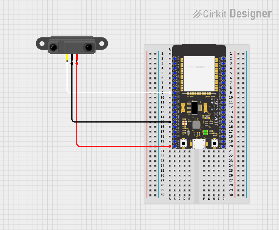
 Open Project in Cirkit Designer
Explore Projects Built with ESP32-WROOM-32UE

 Open Project in Cirkit Designer
 Open Project in Cirkit Designer
 Open Project in Cirkit Designer
 Open Project in Cirkit Designer
Common Applications and Use Cases
- Smart home devices
- Wireless sensors and actuators
- IoT gateways
- Wearable electronics
- Energy management systems
- Robotics
Technical Specifications
Key Technical Details
- Microcontroller: ESP32-D0WD
- Operating Voltage: 3.0V to 3.6V
- Recommended Operating Voltage: 3.3V
- Maximum Current: 500 mA
- Wi-Fi: 802.11 b/g/n (802.11n up to 150 Mbps)
- Bluetooth: v4.2 BR/EDR and BLE specification
- RAM: 520 KB SRAM
- Flash Memory: 4 MB
- Clock Frequency: Up to 240 MHz
- GPIO Pins: 38
- ADC Channels: 18
- DAC Channels: 2
- UART Interfaces: 3
- SPI Interfaces: 4
- I2C Interfaces: 2
- PWM Channels: 16
- Temperature Range: -40°C to +85°C
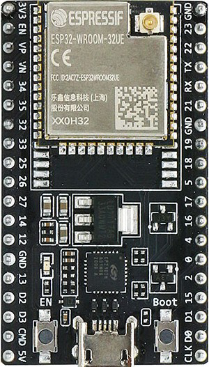
Pin Configuration and Descriptions
| Pin Number | Name | Description |
|---|---|---|
| 1 | 3V3 | Power supply (3.3V) |
| 2 | GND | Ground |
| 3 | EN | Chip enable (active high) |
| ... | ... | ... |
| 38 | IO36 | General purpose IO / ADC channel |
Note: This is a simplified representation of the pinout. Please refer to the manufacturer's datasheet for the complete pinout and pin descriptions.
Usage Instructions
How to Use the Component in a Circuit
- Power Supply: Connect a stable 3.3V power source to the 3V3 and GND pins.
- Enabling the Chip: The EN pin must be pulled high to enable the chip.
- Serial Communication: Connect UART pins (TXD, RXD) to a serial converter or directly to a microcontroller to enable serial communication.
- GPIO Configuration: Configure the GPIO pins according to your application's needs, ensuring that you do not exceed the maximum current ratings.
Important Considerations and Best Practices
- Always use a regulated 3.3V power supply to avoid damaging the module.
- Ensure that the antenna area is clear of metal components to avoid signal interference.
- Use proper decoupling capacitors close to the power supply pins to minimize power supply noise.
- Avoid exposing the module to temperatures outside the specified range.
- When programming the module, ensure that the boot mode is correctly set by configuring the strapping pins (GPIO0, GPIO2, and GPIO15).
Troubleshooting and FAQs
Common Issues Users Might Face
- Module Does Not Power On: Check the power supply and connections to the 3V3 and GND pins.
- Wi-Fi or Bluetooth Not Working: Ensure that the antenna is properly connected and not obstructed.
- Cannot Upload Firmware: Verify that the correct boot mode is set and the UART connection is secure.
Solutions and Tips for Troubleshooting
- If the module is unresponsive, try resetting it by toggling the EN pin.
- For connectivity issues, check the signal strength and ensure there are no sources of interference nearby.
- Use the Espressif Flash Download Tools for firmware updates and troubleshooting flash-related issues.
FAQs
Q: Can the ESP32-WROOM-32UE be used with a 5V power supply? A: No, the module requires a 3.3V power supply. Using a 5V power supply can damage the module.
Q: How many GPIO pins can be used for input/output? A: The module has 38 GPIO pins, but some are used for specific functions. Check the datasheet to determine which pins are available for general use.
Q: Is the ESP32-WROOM-32UE compatible with the Arduino IDE? A: Yes, the module can be programmed using the Arduino IDE with the appropriate board manager installed.
Q: What is the maximum Wi-Fi range of the ESP32-WROOM-32UE? A: The range depends on several factors, including the antenna design, obstructions, and interference. Typically, the range can be up to 150 meters in open space.
Example Code for Arduino UNO
Below is an example of how to use the ESP32-WROOM-32UE with an Arduino UNO for a simple Wi-Fi scan:
#include "WiFi.h"

void setup() {
  Serial.begin(115200);

  // Initialize the WiFi module
  WiFi.mode(WIFI_STA);
  WiFi.disconnect();
  delay(100);

  Serial.println("Setup done");
}

void loop() {
  // WiFi.scanNetworks will return the number of networks found
  Serial.println("Scan start");
  int n = WiFi.scanNetworks();
  Serial.println("Scan done");
  if (n == 0) {
    Serial.println("No networks found");
  } else {
    Serial.print(n);
    Serial.println(" networks found");
    for (int i = 0; i < n; ++i) {
      // Print SSID and RSSI for each network found
      Serial.print(i + 1);
      Serial.print(": ");
      Serial.print(WiFi.SSID(i));
      Serial.print(" (");
      Serial.print(WiFi.RSSI(i));
      Serial.print(")");
      Serial.println((WiFi.encryptionType(i) == WIFI_AUTH_OPEN)?" ":"*");
      delay(10);
    }
  }
  Serial.println("");

  // Wait a bit before scanning again
  delay(5000);
}
This code will perform a Wi-Fi network scan and print the results to the serial monitor. Make sure to select the appropriate board and port in the Arduino IDE before uploading the code to the ESP32 module.