How to Use GPS NEO-M8N with Compass: Examples, Pinouts, and Specs
Introduction
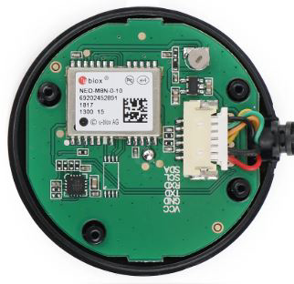
The GPS NEO-M8N, manufactured by u-blox, is a high-performance GNSS (Global Navigation Satellite System) receiver module designed to deliver precise positioning and navigation data. It supports multiple GNSS constellations, including GPS, GLONASS, Galileo, and BeiDou, ensuring reliable and accurate location tracking. Additionally, the module features an integrated compass, enabling orientation and heading information, which is particularly useful for applications requiring directional awareness.
Explore Projects Built with GPS NEO-M8N with Compass


Explore Projects Built with GPS NEO-M8N with Compass
Common Applications and Use Cases
- Drones and UAVs: For precise navigation and waypoint tracking.
- Robotics: To provide location and orientation data for autonomous movement.
- Automotive Systems: For vehicle tracking and navigation.
- Geographic Surveying: For accurate mapping and data collection.
- IoT Devices: For location-based services and tracking.
Technical Specifications
The GPS NEO-M8N module is packed with advanced features and specifications to meet the demands of modern navigation systems.
Key Technical Details
| Parameter | Specification |
|---|---|
| GNSS Support | GPS, GLONASS, Galileo, BeiDou |
| Position Accuracy | 2.5 meters (CEP) |
| Update Rate | Up to 10 Hz |
| Operating Voltage | 2.7V to 3.6V |
| Power Consumption | ~23 mA (continuous tracking mode) |
| Communication Interfaces | UART, I2C, SPI |
| Compass Sensor | Integrated 3-axis magnetometer |
| Operating Temperature | -40°C to +85°C |
| Dimensions | 16 x 12.2 x 2.4 mm |
Pin Configuration and Descriptions
The NEO-M8N module typically comes with a breakout board for easier integration. Below is the pinout description:
| Pin | Name | Description |
|---|---|---|
| 1 | VCC | Power supply input (3.3V recommended). |
| 2 | GND | Ground connection. |
| 3 | TXD | UART Transmit pin (used for serial communication). |
| 4 | RXD | UART Receive pin (used for serial communication). |
| 5 | SDA | I2C Data line (for I2C communication). |
| 6 | SCL | I2C Clock line (for I2C communication). |
| 7 | PPS | Pulse Per Second output (used for time synchronization). |
| 8 | COMPASS_SDA | I2C Data line for the integrated compass. |
| 9 | COMPASS_SCL | I2C Clock line for the integrated compass. |
| 10 | ANT | External antenna connection (optional, for improved signal reception). |
Usage Instructions
The GPS NEO-M8N module is versatile and can be used in a variety of projects. Below are the steps and considerations for integrating it into your circuit.
How to Use the Component in a Circuit
- Power Supply: Connect the VCC pin to a 3.3V power source and GND to ground.
- Communication Interface: Choose between UART, I2C, or SPI for communication:
- For UART, connect the TXD and RXD pins to the corresponding pins on your microcontroller.
- For I2C, connect the SDA and SCL pins to the I2C bus of your microcontroller.
- Compass Integration: Use the COMPASS_SDA and COMPASS_SCL pins to communicate with the integrated compass via I2C.
- Antenna: If required, connect an external antenna to the ANT pin for better signal reception.
- Software Setup: Use libraries such as TinyGPS++ (for GPS) and a magnetometer library (for the compass) to process data.
Important Considerations and Best Practices
- Antenna Placement: Ensure the antenna has a clear view of the sky for optimal satellite reception.
- Power Stability: Use a stable power supply to avoid performance issues.
- Compass Calibration: Calibrate the compass in your application to ensure accurate heading data.
- Baud Rate: The default UART baud rate is 9600. Configure your microcontroller accordingly.
- Update Rate: Adjust the update rate (e.g., 1 Hz, 5 Hz, or 10 Hz) based on your application’s requirements.
Example: Connecting to an Arduino UNO
Below is an example of how to connect the GPS NEO-M8N to an Arduino UNO and read GPS data using the TinyGPS++ library.
Wiring
| NEO-M8N Pin | Arduino UNO Pin |
|---|---|
| VCC | 3.3V |
| GND | GND |
| TXD | RX (Pin 0) |
| RXD | TX (Pin 1) |
Code Example
#include <TinyGPS++.h>
#include <SoftwareSerial.h>

// Create a TinyGPS++ object to parse GPS data
TinyGPSPlus gps;

// Define RX and TX pins for SoftwareSerial
SoftwareSerial gpsSerial(4, 3); // RX = Pin 4, TX = Pin 3

void setup() {
  Serial.begin(9600); // Initialize Serial Monitor
  gpsSerial.begin(9600); // Initialize GPS module communication

  Serial.println("GPS NEO-M8N Test");
}

void loop() {
  // Read data from GPS module
  while (gpsSerial.available() > 0) {
    char c = gpsSerial.read();
    gps.encode(c); // Parse GPS data

    // If a valid location is available, print it
    if (gps.location.isUpdated()) {
      Serial.print("Latitude: ");
      Serial.print(gps.location.lat(), 6);
      Serial.print(", Longitude: ");
      Serial.println(gps.location.lng(), 6);
    }
  }
}
Notes
- Use SoftwareSerial if the hardware UART pins are occupied.
- Ensure the GPS module has a clear view of the sky for accurate data.
Troubleshooting and FAQs
Common Issues and Solutions
No GPS Fix:
- Cause: Poor satellite reception.
- Solution: Move the antenna to an open area with a clear view of the sky.
Incorrect Compass Readings:
- Cause: Magnetic interference from nearby components.
- Solution: Place the module away from magnetic sources and recalibrate the compass.
No Data Output:
- Cause: Incorrect wiring or baud rate mismatch.
- Solution: Verify connections and ensure the baud rate matches the module's default (9600).
Slow Update Rate:
- Cause: Default update rate is set to 1 Hz.
- Solution: Configure the module to a higher update rate (e.g., 5 Hz or 10 Hz) using u-blox's u-center software.
FAQs
Q: Can the NEO-M8N work indoors?
A: The module may work indoors near windows, but performance is significantly reduced.Q: How do I calibrate the compass?
A: Use a magnetometer calibration library or perform a figure-eight motion to recalibrate.Q: Can I use the module with 5V logic?
A: The NEO-M8N operates at 3.3V. Use a level shifter if interfacing with 5V logic devices.Q: What is the maximum number of satellites it can track?
A: The NEO-M8N can track up to 72 channels simultaneously.
This documentation provides a comprehensive guide to using the GPS NEO-M8N with Compass module effectively in your projects.