Cirkit Designer Logo
Cirkit Designer
Your all-in-one circuit design IDE
Home / 
Component Documentation

How to Use mp2307: Examples, Pinouts, and Specs

Image of mp2307
Cirkit Designer LogoDesign with mp2307 in Cirkit Designer

Introduction

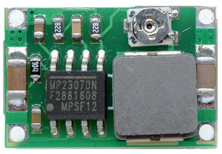
The MP2307, manufactured by GK, is a high-efficiency step-down (buck) voltage regulator designed to convert a higher input voltage to a lower output voltage. It is compact, reliable, and widely used in applications requiring efficient power conversion. The MP2307 features a wide input voltage range, adjustable output voltage, and integrated protection mechanisms such as overcurrent and thermal shutdown, making it suitable for a variety of electronic projects.

Explore Projects Built with mp2307

Use Cirkit Designer to design, explore, and prototype these projects online. Some projects support real-time simulation. Click "Open Project" to start designing instantly!
Arduino Mega 2560 Based Security System with Fingerprint Authentication and SMS Alerts
Image of Door security system: A project utilizing mp2307 in a practical application
This circuit features an Arduino Mega 2560 microcontroller interfaced with a SIM800L GSM module, two fingerprint scanners, an I2C LCD display, an IR sensor, and a piezo buzzer. Power management is handled by a PowerBoost 1000 Basic Pad USB, a TP4056 charging module, and a Li-ion 18650 battery, with an option to use a Mini AC-DC 110V-230V to 5V 700mA module for direct power supply. The primary functionality appears to be a security system with GSM communication capabilities, biometric access control, and visual/audible feedback.
Cirkit Designer LogoOpen Project in Cirkit Designer
ESP32-Based Battery-Powered Multi-Sensor System
Image of Dive sense: A project utilizing mp2307 in a practical application
This circuit consists of a TP4056 module connected to a 3.7V LiPo battery, providing a charging interface for the battery. The TP4056 manages the charging process by connecting its B+ and B- pins to the battery's positive and ground terminals, respectively.
Cirkit Designer LogoOpen Project in Cirkit Designer
Arduino Nano 33 BLE Battery-Powered Display Interface
Image of senior design 1: A project utilizing mp2307 in a practical application
This circuit features a Nano 33 BLE microcontroller interfaced with a TM1637 4-digit 7-segment display for information output, powered by a 3.7V battery managed by a TP4056 charging module. The microcontroller communicates with the display to present data, while the TP4056 ensures the battery is charged safely and provides power to the system.
Cirkit Designer LogoOpen Project in Cirkit Designer
I2C-Controlled Relay Switching with ESP32 and MCP23017 for Home Automation
Image of Vloerverwarming: A project utilizing mp2307 in a practical application
This circuit appears to be a control system utilizing two MCP23017 I/O expanders interfaced with an Olimex ESP32-EVB microcontroller via I2C communication, as indicated by the SDA and SCL connections with pull-up resistors. The MCP23017 expanders control an 8-channel relay module, allowing the microcontroller to switch various loads, potentially for home automation or industrial control. Additionally, there is an Adafruit ADS1115 16-bit ADC for analog signal measurement, and several heating actuators and a thermostat are connected, suggesting temperature control functionality.
Cirkit Designer LogoOpen Project in Cirkit Designer

Explore Projects Built with mp2307

Use Cirkit Designer to design, explore, and prototype these projects online. Some projects support real-time simulation. Click "Open Project" to start designing instantly!
Image of Door security system: A project utilizing mp2307 in a practical application
Arduino Mega 2560 Based Security System with Fingerprint Authentication and SMS Alerts
This circuit features an Arduino Mega 2560 microcontroller interfaced with a SIM800L GSM module, two fingerprint scanners, an I2C LCD display, an IR sensor, and a piezo buzzer. Power management is handled by a PowerBoost 1000 Basic Pad USB, a TP4056 charging module, and a Li-ion 18650 battery, with an option to use a Mini AC-DC 110V-230V to 5V 700mA module for direct power supply. The primary functionality appears to be a security system with GSM communication capabilities, biometric access control, and visual/audible feedback.
Cirkit Designer LogoOpen Project in Cirkit Designer
Image of Dive sense: A project utilizing mp2307 in a practical application
ESP32-Based Battery-Powered Multi-Sensor System
This circuit consists of a TP4056 module connected to a 3.7V LiPo battery, providing a charging interface for the battery. The TP4056 manages the charging process by connecting its B+ and B- pins to the battery's positive and ground terminals, respectively.
Cirkit Designer LogoOpen Project in Cirkit Designer
Image of senior design 1: A project utilizing mp2307 in a practical application
Arduino Nano 33 BLE Battery-Powered Display Interface
This circuit features a Nano 33 BLE microcontroller interfaced with a TM1637 4-digit 7-segment display for information output, powered by a 3.7V battery managed by a TP4056 charging module. The microcontroller communicates with the display to present data, while the TP4056 ensures the battery is charged safely and provides power to the system.
Cirkit Designer LogoOpen Project in Cirkit Designer
Image of Vloerverwarming: A project utilizing mp2307 in a practical application
I2C-Controlled Relay Switching with ESP32 and MCP23017 for Home Automation
This circuit appears to be a control system utilizing two MCP23017 I/O expanders interfaced with an Olimex ESP32-EVB microcontroller via I2C communication, as indicated by the SDA and SCL connections with pull-up resistors. The MCP23017 expanders control an 8-channel relay module, allowing the microcontroller to switch various loads, potentially for home automation or industrial control. Additionally, there is an Adafruit ADS1115 16-bit ADC for analog signal measurement, and several heating actuators and a thermostat are connected, suggesting temperature control functionality.
Cirkit Designer LogoOpen Project in Cirkit Designer

Common Applications

  • Power supply modules for microcontrollers and development boards (e.g., Arduino, Raspberry Pi)
  • Battery-powered devices
  • LED drivers
  • Industrial control systems
  • Consumer electronics

Technical Specifications

Key Technical Details

Parameter Value
Input Voltage Range 4.75V to 23V
Output Voltage Range 0.92V to 20V (adjustable)
Output Current Up to 3A
Efficiency Up to 95%
Switching Frequency 340 kHz
Operating Temperature -40°C to +85°C
Protection Features Overcurrent, thermal shutdown
Package Type SOIC-8 (with exposed pad)

Pin Configuration and Descriptions

Pin Number Pin Name Description
1 VIN Input voltage pin (4.75V to 23V). Connect to the input power source.
2 SW Switching node. Connect to the inductor.
3 GND Ground pin. Connect to the system ground.
4 FB Feedback pin. Used to set the output voltage via a resistor divider.
5 EN Enable pin. Pull high to enable the regulator, or low to disable it.
6 NC No connection. Leave this pin unconnected.
7 NC No connection. Leave this pin unconnected.
8 BST Bootstrap pin. Connect a capacitor (typically 0.1µF) between BST and SW.

Usage Instructions

How to Use the MP2307 in a Circuit

  1. Input Voltage: Connect the input voltage (4.75V to 23V) to the VIN pin. Ensure the input voltage is within the specified range.
  2. Output Voltage Adjustment: Use a resistor divider network connected to the FB pin to set the desired output voltage. The formula for the output voltage is: [ V_{OUT} = 0.92 \times \left(1 + \frac{R1}{R2}\right) ] where ( R1 ) and ( R2 ) are the resistors in the divider.
  3. Inductor Selection: Choose an inductor with a suitable current rating (greater than the output current) and low DC resistance for optimal efficiency.
  4. Capacitors: Add input and output capacitors to stabilize the circuit. Typical values are:
    • Input capacitor: 10µF to 22µF
    • Output capacitor: 22µF to 47µF
  5. Bootstrap Capacitor: Connect a 0.1µF ceramic capacitor between the BST and SW pins.
  6. Enable Pin: Pull the EN pin high (above 1.5V) to enable the regulator. Pull it low to disable it.

Important Considerations and Best Practices

  • Ensure proper heat dissipation by using a PCB with a good thermal design, especially for high-current applications.
  • Use low-ESR capacitors for better performance and stability.
  • Keep the feedback resistor divider and other sensitive components close to the IC to minimize noise.
  • Avoid exceeding the maximum input voltage (23V) or output current (3A) to prevent damage.

Example: Using MP2307 with Arduino UNO

The MP2307 can be used to power an Arduino UNO by stepping down a 12V input to 5V. Below is an example circuit and Arduino code to demonstrate its use.

Circuit Connections

  • Connect a 12V power source to the VIN pin of the MP2307.
  • Set the output voltage to 5V using a resistor divider (e.g., ( R1 = 6.8k\Omega ), ( R2 = 1.2k\Omega )).
  • Connect the output of the MP2307 to the 5V pin of the Arduino UNO.
  • Connect the GND pin of the MP2307 to the Arduino GND.

Arduino Code Example

// Example code to blink an LED using Arduino UNO powered by MP2307
// Ensure the MP2307 output is set to 5V before connecting to the Arduino

const int ledPin = 13; // Built-in LED pin on Arduino UNO

void setup() {
  pinMode(ledPin, OUTPUT); // Set LED pin as output
}

void loop() {
  digitalWrite(ledPin, HIGH); // Turn the LED on
  delay(1000);                // Wait for 1 second
  digitalWrite(ledPin, LOW);  // Turn the LED off
  delay(1000);                // Wait for 1 second
}

Troubleshooting and FAQs

Common Issues and Solutions

  1. No Output Voltage

    • Cause: The EN pin is not pulled high.
    • Solution: Ensure the EN pin is connected to a voltage above 1.5V to enable the regulator.
  2. Output Voltage is Incorrect

    • Cause: Incorrect resistor values in the feedback network.
    • Solution: Verify the resistor values and recalculate using the output voltage formula.
  3. Overheating

    • Cause: Excessive current draw or poor thermal dissipation.
    • Solution: Ensure the load current does not exceed 3A and improve PCB thermal design.
  4. High Output Ripple

    • Cause: Insufficient or poor-quality capacitors.
    • Solution: Use low-ESR capacitors with appropriate values for input and output.

FAQs

  1. Can the MP2307 be used with a 24V input?

    • No, the maximum input voltage is 23V. Exceeding this limit may damage the component.
  2. What is the minimum output voltage of the MP2307?

    • The minimum output voltage is 0.92V, which is determined by the internal reference voltage.
  3. Can I use the MP2307 without a heatsink?

    • Yes, for low-current applications. However, for higher currents, ensure proper heat dissipation through PCB design.
  4. Is the MP2307 suitable for battery-powered devices?

    • Yes, its high efficiency makes it ideal for battery-powered applications.

By following this documentation, you can effectively integrate the MP2307 into your projects for efficient and reliable power conversion.