How to Use 12v SOLENOID LOCK: Examples, Pinouts, and Specs
12V Solenoid Lock Documentation
1. Introduction
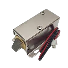
The 12V Solenoid Lock (Manufacturer: AC, Part ID: Solenoid Lock) is an electromechanical device designed to provide secure locking and unlocking functionality. It operates using an electromagnetic coil that, when energized with a 12V DC power supply, retracts the locking mechanism, allowing access. When the power is removed, the lock returns to its default locked state via a spring mechanism.
Common Applications
- Access Control Systems: Used in doors, cabinets, and lockers for secure access.
- Vending Machines: To control access to compartments.
- Automated Systems: For robotics, smart home devices, and industrial equipment.
- Security Systems: As part of electronic locking mechanisms in safes or secure enclosures.
The 12V Solenoid Lock is compact, reliable, and easy to integrate into various electronic systems, making it a popular choice for both DIY projects and professional applications.
2. Technical Specifications
The following table outlines the key technical details of the 12V Solenoid Lock:
| Parameter | Specification |
|---|---|
| Operating Voltage | 12V DC |
| Operating Current | 0.8A (800mA) |
| Power Consumption | ~9.6W |
| Lock Type | Spring-loaded, fail-secure (locked when unpowered) |
| Material | Metal casing with plastic components |
| Dimensions | 54mm x 42mm x 28mm |
| Weight | ~150g |
| Activation Time | Continuous operation up to 10 seconds (recommended) |
| Wire Length | ~25cm |
| Mounting Holes | 2 holes for screws (M3 size) |
Pin Configuration and Descriptions
The 12V Solenoid Lock has two wires for connection:
| Wire Color | Description |
|---|---|
| Red | Positive terminal (+12V DC) |
| Black | Negative terminal (Ground) |
3. Usage Instructions
Connecting the Solenoid Lock to a Circuit
- Power Supply: Ensure you have a 12V DC power source capable of supplying at least 1A of current.
- Polarity: Connect the red wire to the positive terminal of the power supply and the black wire to the ground.
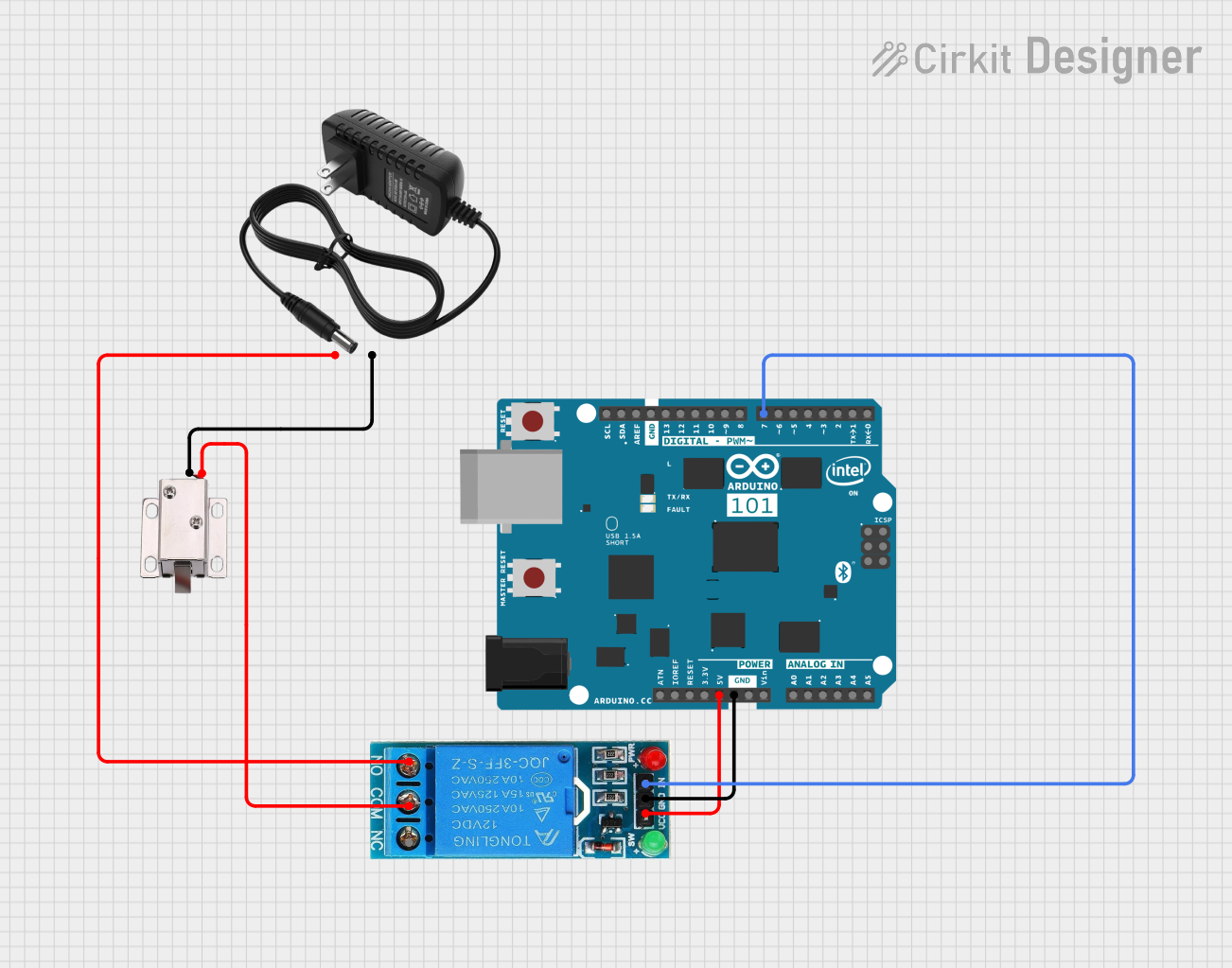
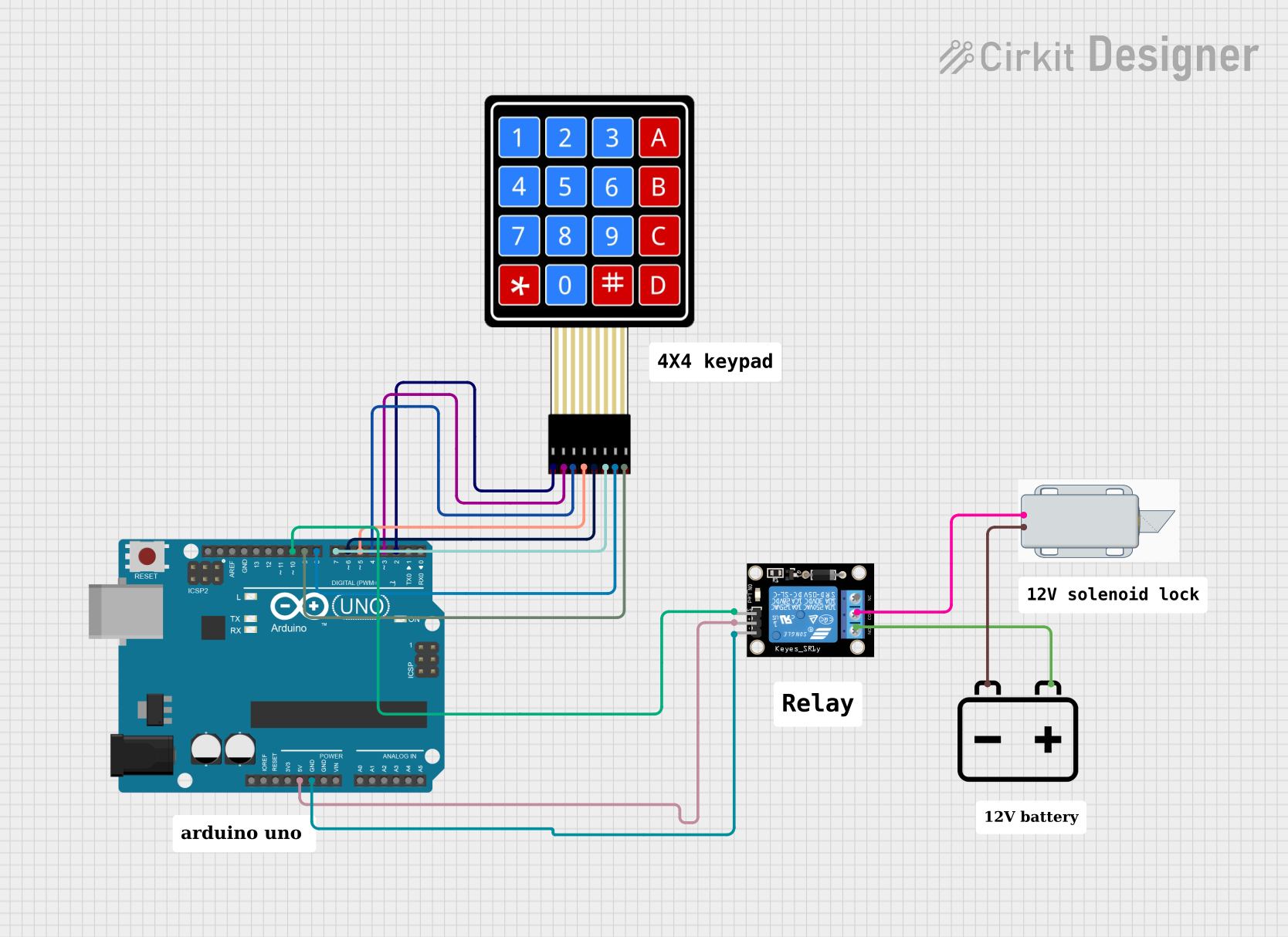
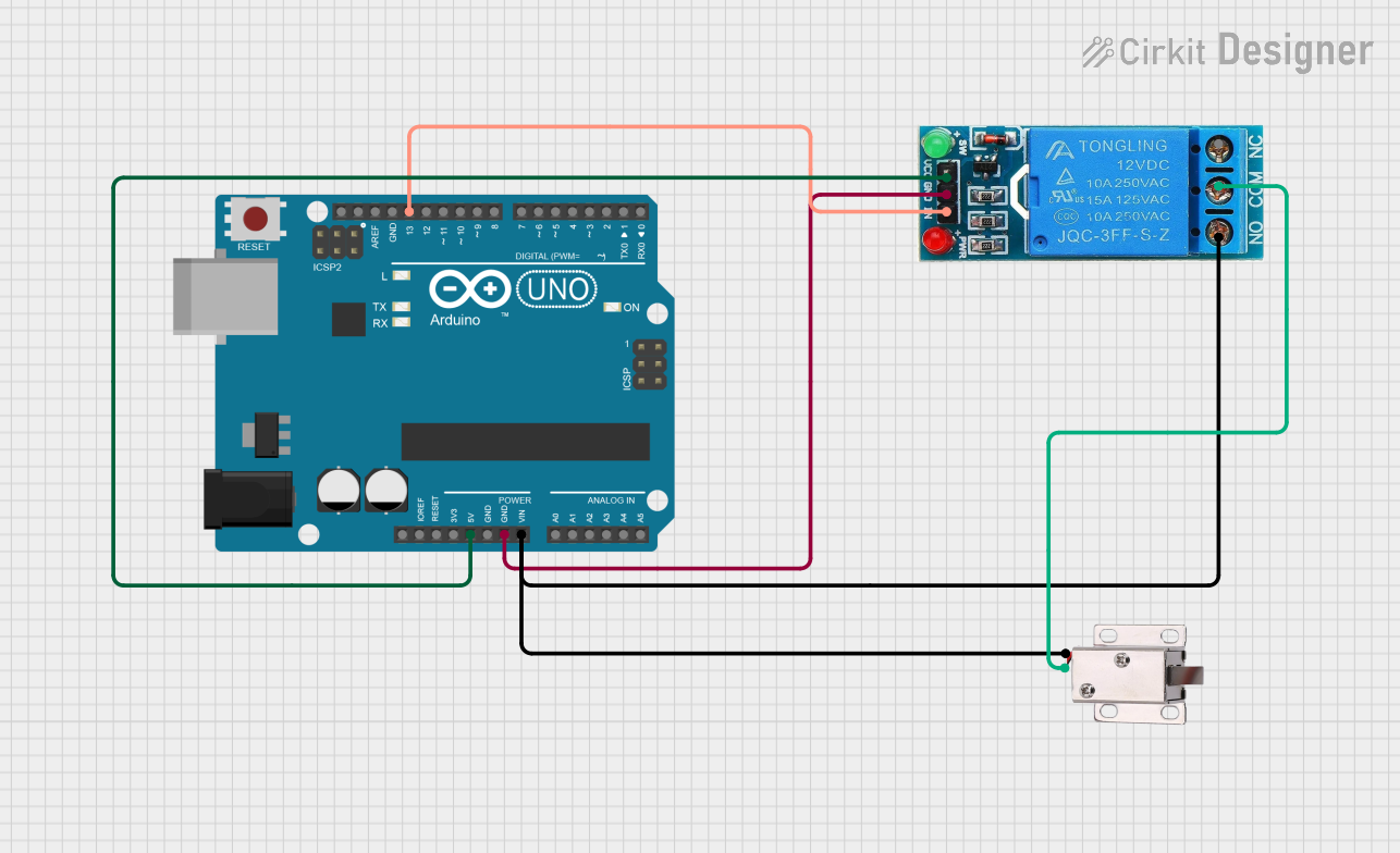
- Control Circuit: Use a transistor, relay, or MOSFET to control the solenoid lock from a microcontroller (e.g., Arduino UNO). Directly connecting the solenoid to a microcontroller is not recommended due to high current requirements.
- Diode Protection: Place a flyback diode (e.g., 1N4007) across the solenoid terminals to protect the circuit from voltage spikes caused by the collapsing magnetic field when the solenoid is turned off.
Example Circuit Diagram
Below is a basic circuit diagram for controlling the solenoid lock using an NPN transistor and an Arduino UNO:
 +12V DC
   |
   +----->|----+
          Diode |
                |
               ( )
               ( ) Solenoid Lock
               ( )
                |
                +-----> Transistor Collector (C)
                |
               [R] Base Resistor (1kΩ)
                |
 Arduino Pin ----+
                |
               GND
Arduino Code Example
The following code demonstrates how to control the solenoid lock using an Arduino UNO:
// Define the pin connected to the transistor's base
const int solenoidPin = 7;

void setup() {
  // Set the solenoid pin as an output
  pinMode(solenoidPin, OUTPUT);
}

void loop() {
  // Activate the solenoid lock (unlock)
  digitalWrite(solenoidPin, HIGH);
  delay(5000); // Keep the lock open for 5 seconds

  // Deactivate the solenoid lock (lock)
  digitalWrite(solenoidPin, LOW);
  delay(5000); // Keep the lock closed for 5 seconds
}
Note: Ensure the solenoid is not powered for extended periods to prevent overheating.
4. Important Considerations and Best Practices
- Power Supply: Use a stable 12V DC power source with sufficient current capacity (at least 1A).
- Heat Management: Avoid continuous activation for more than 10 seconds to prevent overheating.
- Flyback Diode: Always use a flyback diode to protect your circuit from voltage spikes.
- Mounting: Secure the solenoid lock using the provided mounting holes to ensure proper alignment and operation.
- Polarity: Double-check the polarity of the connections to avoid damage to the solenoid.
5. Troubleshooting and FAQs
Common Issues and Solutions
| Issue | Possible Cause | Solution |
|---|---|---|
| Solenoid does not activate | Incorrect wiring or insufficient power | Verify connections and ensure a 12V DC supply with at least 1A current. |
| Solenoid gets hot quickly | Continuous activation for too long | Limit activation time to 10 seconds or less. |
| Circuit damage after activation | Missing flyback diode | Install a flyback diode across the solenoid terminals. |
| Solenoid makes a buzzing noise | Unstable power supply | Use a regulated 12V DC power source. |
| Lock does not return to locked state | Spring mechanism is stuck or damaged | Inspect the spring and ensure it is not obstructed. Replace if necessary. |
Frequently Asked Questions (FAQs)
Can I use a 5V power supply instead of 12V?
- No, the solenoid lock is designed to operate at 12V DC. Using a lower voltage will result in insufficient force to retract the lock.
Can I control the solenoid lock directly from an Arduino?
- No, the solenoid requires more current than the Arduino can supply. Use a transistor, relay, or MOSFET to control the solenoid.
What happens if I reverse the polarity of the wires?
- Reversing the polarity may damage the solenoid. Always connect the red wire to the positive terminal and the black wire to ground.
Can the solenoid lock be used outdoors?
- The solenoid lock is not weatherproof. If used outdoors, ensure it is enclosed in a waterproof housing.
6. Conclusion
The 12V Solenoid Lock is a versatile and reliable component for secure locking applications. By following the guidelines in this documentation, you can safely and effectively integrate the solenoid lock into your projects. Whether you're building an access control system or a smart home device, this component offers a robust solution for your locking needs.
Explore Projects Built with 12v SOLENOID LOCK
Explore Projects Built with 12v SOLENOID LOCK