
How to Use Adafruit LIS2MDL: Examples, Pinouts, and Specs
 Design with Adafruit LIS2MDL in Cirkit Designer
Introduction
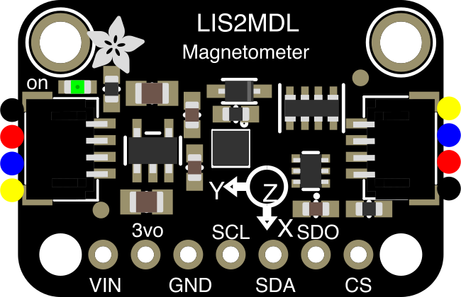
The Adafruit LIS2MDL (Part ID: 4488) is a high-performance 3-axis magnetometer sensor designed to measure magnetic fields with precision. It is ideal for applications such as navigation, orientation detection, augmented reality, and electronic compasses. The sensor communicates via the I2C interface, making it easy to integrate with microcontrollers and development boards like the Arduino UNO. Its low power consumption makes it particularly suitable for portable and battery-operated devices.
Explore Projects Built with Adafruit LIS2MDL
 Open Project in Cirkit Designer
 Open Project in Cirkit Designer
 Open Project in Cirkit Designer
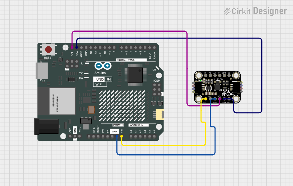 Open Project in Cirkit Designer
Explore Projects Built with Adafruit LIS2MDL
Open Project in Cirkit DesignerOpen Project in Cirkit DesignerOpen Project in Cirkit DesignerOpen Project in Cirkit DesignerTechnical Specifications
The following table outlines the key technical specifications of the Adafruit LIS2MDL:
| Parameter | Value |
|---|---|
| Operating Voltage | 3.3V or 5V (logic level compatible) |
| Communication Interface | I2C |
| I2C Address | 0x1E (default) |
| Magnetic Field Range | ±50 gauss |
| Output Data Rate (ODR) | 10 Hz to 100 Hz |
| Power Consumption | 260 µA (typical) |
| Operating Temperature | -40°C to +85°C |
| Dimensions | 20mm x 18mm x 2mm |
Pin Configuration and Descriptions
The Adafruit LIS2MDL breakout board has the following pinout:
| Pin Name | Description |
|---|---|
| VIN | Power input (3.3V or 5V). Provides power to the sensor. |
| GND | Ground. Connect to the ground of your circuit. |
| SCL | I2C clock line. Connect to the SCL pin of your microcontroller. |
| SDA | I2C data line. Connect to the SDA pin of your microcontroller. |
| DRDY | Data Ready pin (optional). Indicates when new data is available. |
| INT | Interrupt pin (optional). Can be configured for specific interrupt events. |
Usage Instructions
Connecting the Adafruit LIS2MDL to an Arduino UNO
To use the Adafruit LIS2MDL with an Arduino UNO, follow these steps:
Wiring:
- Connect the
VINpin of the LIS2MDL to the 5V pin on the Arduino UNO. - Connect the
GNDpin of the LIS2MDL to the GND pin on the Arduino UNO. - Connect the
SCLpin of the LIS2MDL to the A5 pin on the Arduino UNO (I2C clock line). - Connect the
SDApin of the LIS2MDL to the A4 pin on the Arduino UNO (I2C data line).
- Connect the
Install the Adafruit LIS2MDL Library:
- Open the Arduino IDE.
- Go to Sketch > Include Library > Manage Libraries.
- Search for "Adafruit LIS2MDL" and install the library.
Upload Example Code: Use the following example code to read magnetic field data from the LIS2MDL:
#include <Wire.h>
#include <Adafruit_LIS2MDL.h>

// Create an instance of the LIS2MDL sensor
Adafruit_LIS2MDL lis2mdl;

void setup() {
  Serial.begin(115200);
  while (!Serial) {
    delay(10); // Wait for Serial Monitor to open
  }

  // Initialize the LIS2MDL sensor
  if (!lis2mdl.begin_I2C()) {
    Serial.println("Failed to find LIS2MDL chip!");
    while (1) {
      delay(10); // Halt if sensor initialization fails
    }
  }
  Serial.println("LIS2MDL initialized successfully!");

  // Set the output data rate (ODR) to 100 Hz
  lis2mdl.setDataRate(LIS2MDL_DATARATE_100_HZ);
}

void loop() {
  // Read magnetic field data
  sensors_event_t event;
  lis2mdl.getEvent(&event);

  // Print magnetic field values in microteslas (µT)
  Serial.print("X: "); Serial.print(event.magnetic.x); Serial.print(" µT, ");
  Serial.print("Y: "); Serial.print(event.magnetic.y); Serial.print(" µT, ");
  Serial.print("Z: "); Serial.print(event.magnetic.z); Serial.println(" µT");

  delay(100); // Delay for readability
}
Important Considerations and Best Practices
- Power Supply: Ensure the sensor is powered with a stable 3.3V or 5V supply.
- I2C Pull-Up Resistors: The breakout board includes pull-up resistors on the I2C lines. If you experience communication issues, ensure there are no conflicting pull-ups in your circuit.
- Magnetic Interference: Avoid placing the sensor near strong magnetic fields or ferromagnetic materials, as they can affect accuracy.
- Data Ready Pin: Use the
DRDYpin for precise timing when reading data, especially in high-speed applications.
Troubleshooting and FAQs
Common Issues
Sensor Not Detected:
- Cause: Incorrect wiring or I2C address mismatch.
- Solution: Double-check the wiring and ensure the I2C address is set to 0x1E in your code.
Inaccurate Readings:
- Cause: Magnetic interference or improper calibration.
- Solution: Calibrate the sensor by rotating it in all directions to account for hard and soft iron distortions.
No Data Output:
- Cause: Incorrect library installation or initialization failure.
- Solution: Verify that the Adafruit LIS2MDL library is installed and that the
begin_I2C()function returnstrue.
FAQs
Q: Can the LIS2MDL be used with 3.3V logic microcontrollers?
A: Yes, the breakout board is compatible with both 3.3V and 5V logic levels.
Q: How do I change the I2C address of the LIS2MDL?
A: The LIS2MDL has a fixed I2C address of 0x1E and does not support address modification.
Q: What is the maximum distance between the LIS2MDL and the microcontroller?
A: The maximum distance depends on the I2C bus speed and pull-up resistor values. For standard I2C speeds (100 kHz), a distance of up to 1 meter is typically reliable.
By following this documentation, you can effectively integrate and utilize the Adafruit LIS2MDL in your projects.